5.4 Details of Function Codes
5-250
Customizable Logic (Mode selection) (U00)
It specifies whether to enable the sequence configured with the customizable logic function or disable it to
run the inverter only via its input terminals and others.
Table 5.4-176
Data for U00 Function
0
Disable
1
Enable (Customizable logic operation)
Customizable Logic (Operation Setting) (U01 to U50)
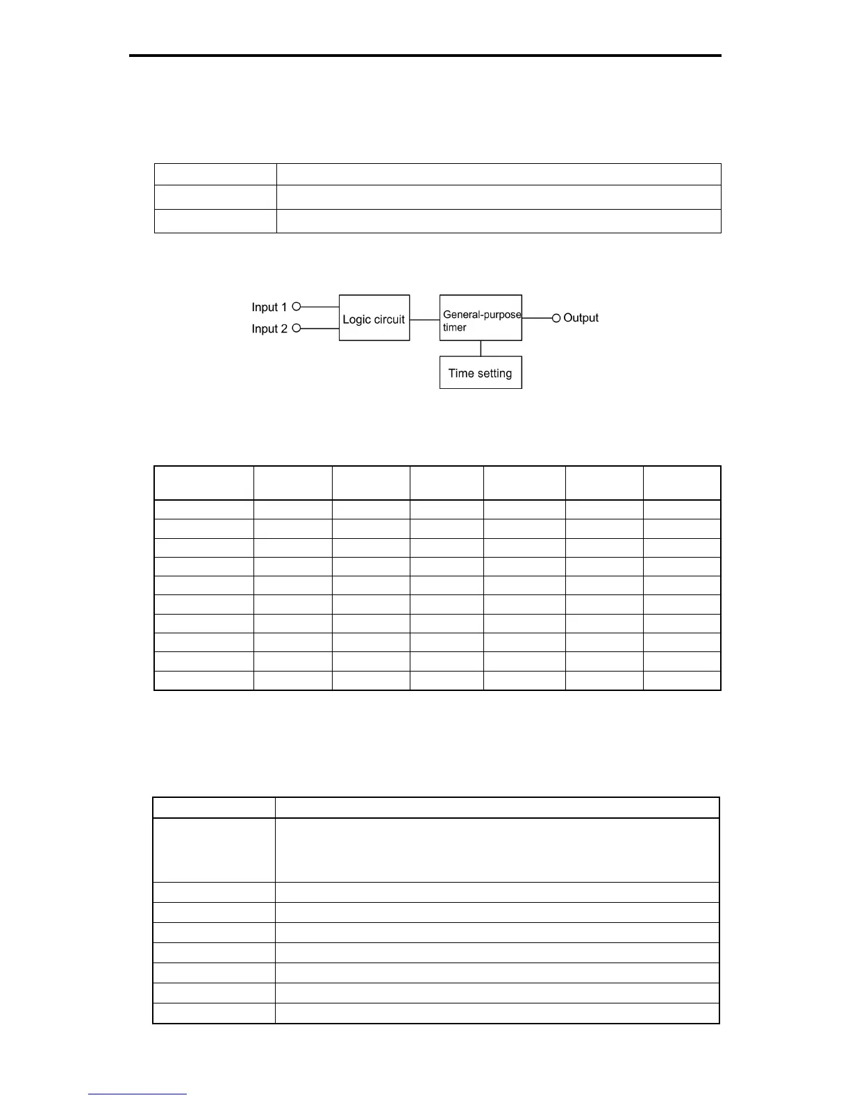
In a customizable logic, one step is composed of the components shown in the following block diagram.
Fig. 5.4-127
Table 5.4-177 Setting of function codes for each step
Step No. Input 1 Input 2 Logic circuit General-purpose
timer
Time setting Output
Note)
Step 1 U01 U02 U03 U04 U05 SO01
Step 2 U06 U07 U08 U09 U10 SO02
Step 3 U11 U12 U13 U14 U15 SO03
Step 4 U16 U17 U18 U19 U20 SO04
Step 5 U21 U22 U23 U24 U25 SO05
Step 6 U26 U27 U28 U29 U30 SO06
Step 7 U31 U32 U33 U34 U35 SO07
Step 8 U36 U37 U38 U39 U40 SO08
Step 9 U41 U42 U43 U44 U45 SO09
Step 10 U46 U47 U48 U49 U50 SO10
Note) Output is not the function code It indicates the output signal signs.
Inputs 1 and 2 (U01, U02, etc.)
The following signals are available as input signals.
Table 5.4-178
Data Selectable Signal
0000 (1000)
to
0105 (1105)
General-purpose output signals (Same as signals used in E20: RUN during running, FAR
frequency (speed) arrival signal, FDT frequency (speed) detected, LU while stopping in
undervoltage, B/D Torque polarity detected)
Note) 27 (Universal DO) is not available.
2001 (3001) Output of step 1 SO01
2002 (3002) Output of step 2 SO02
2003 (3003) Output of step 3 SO03
2004 (3004) Output of step 4 SO04
2005 (3005) Output of step 5 SO05
2006 (3006) Output of step 6 SO06
2007 (3007) Output of step 7 SO07

 Loading...


