5.4 Details of Function Codes
5-255
Chapter 5 Function Code
Details of
Function Codes
F codes
E codes
C codes
P codes
H codes
A codes
b codes
r codes
J codes
d codes
U00 to U91
y codes
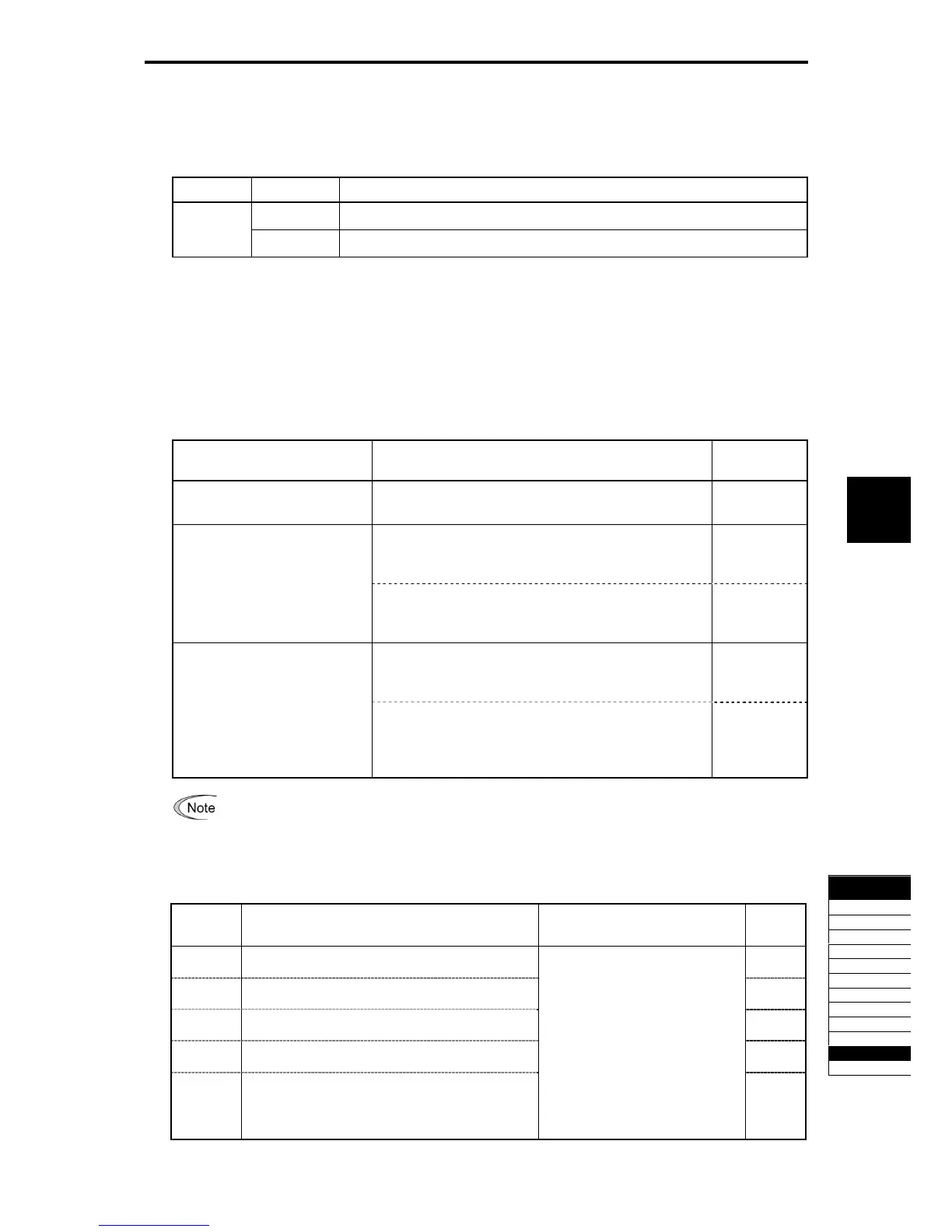
Time setting (U05, etc.)
Setting of the general-purpose timer and setting of count number of the up/down counter are possible.
Table 5.4-181
Data Function Description
Timer period
The period is specified by seconds.
0.00 to 600.00
Counter value
The specified value is multiplied by 100 times. (If 0.01 is specified, it is converted to 1.)
Output Signal
Each step of the customizable logic is output to S001 to S010.
Settings of output s001 to S010 are different depending on the connecting target as shown in the following
table. (When connecting to any function other than the customizable logic, connect via the customizable
logic output (CL01 to CL05).
Table 5.4-182
Connecting destination of output of
each step
Setting Method Function Code
Customizable logic input
By using the customizable logic input setting, select an
internal step output signal SO01 to SO10.
U01, U02, etc.
Select one of the internal step output signals SO01 to SO10 to
be connected to customizable logic output signals 1 to 5
(CLO1 to CLO5).
U71 to U75
Input to the inverter's sequence
process
("Select multi-frequency" SS1, Run
forward FWD, etc.)
Selects an input function of the inverter sequence process
connecting to the customizable logic output signals 1 or 5
(CLO1 to CLO5). (Same as in E01)
U81 to U85
Select the internal step output signals SO01 to SO10 to be
connected to customizable logic output signals 1 to 5 (CLO1
to CLO5).
U71 to U75
General-purpose digital output
(terminal [Y])
To set the general-purpose output (terminal [Y]) to be
connected to the customizable logic output signal 1 to 5
(CL01 to CL05), select CL01 to CL05 at the general purpose
digital output (terminal [Y]) function selection side.
E20 to E24,
E27
The general-purpose digital output (terminal [Y]) updates the data in 5 ms interval. To surely output
the customizable logic signal, turn on the on-delay and off-delay. Otherwise, short ON/OFF signal
may not be reflected on terminal [Y].
Table 5.4-183
Function
Code
Name Data Setting Range Default
Setting
U71
Customizable logic output signal 1 (Output selection)
0
U72
Customizable logic output signal 2 (Output selection)
0
U73
Customizable logic output signal 3 (Output selection)
0
U74
Customizable logic output signal 4 (Output selection)
0
U75
Customizable logic output signal 5 (Output selection)
0: Disable
1: Output of step 1 SO01
2: Output of step 2 SO02
3: Output of step 3 SO03
4: Output of step 4 SO04
5: Output of step 5 SO05
6: Output of step 6 SO06
7: Output of step 7 SO07
8: Output of step 8 SO08
9: Output of step 9 SO09
10: Output of step 10 SO10
0

 Loading...


