5.4 Details of Function Codes
5-256
Function
Code
Name Data Setting Range Default
Setting
U81 Customizable logic output signal 1 (Function selection)
100
U82
Customizable logic output signal 2 (Function selection)
100
U83
Customizable logic output signal 3 (Function selection)
100
U84
Customizable logic output signal 4 (Function selection)
100
U85
Customizable logic output signal 5 (Function selection)
0 to 100, 1000 to 1081
(Same as terminal function selection
of E98 and E99)
However, the following functions
cannot be selected.
19 (1019): Edit accept command
(Data change possible)
80 (1080): Cancel customizable
logic
100
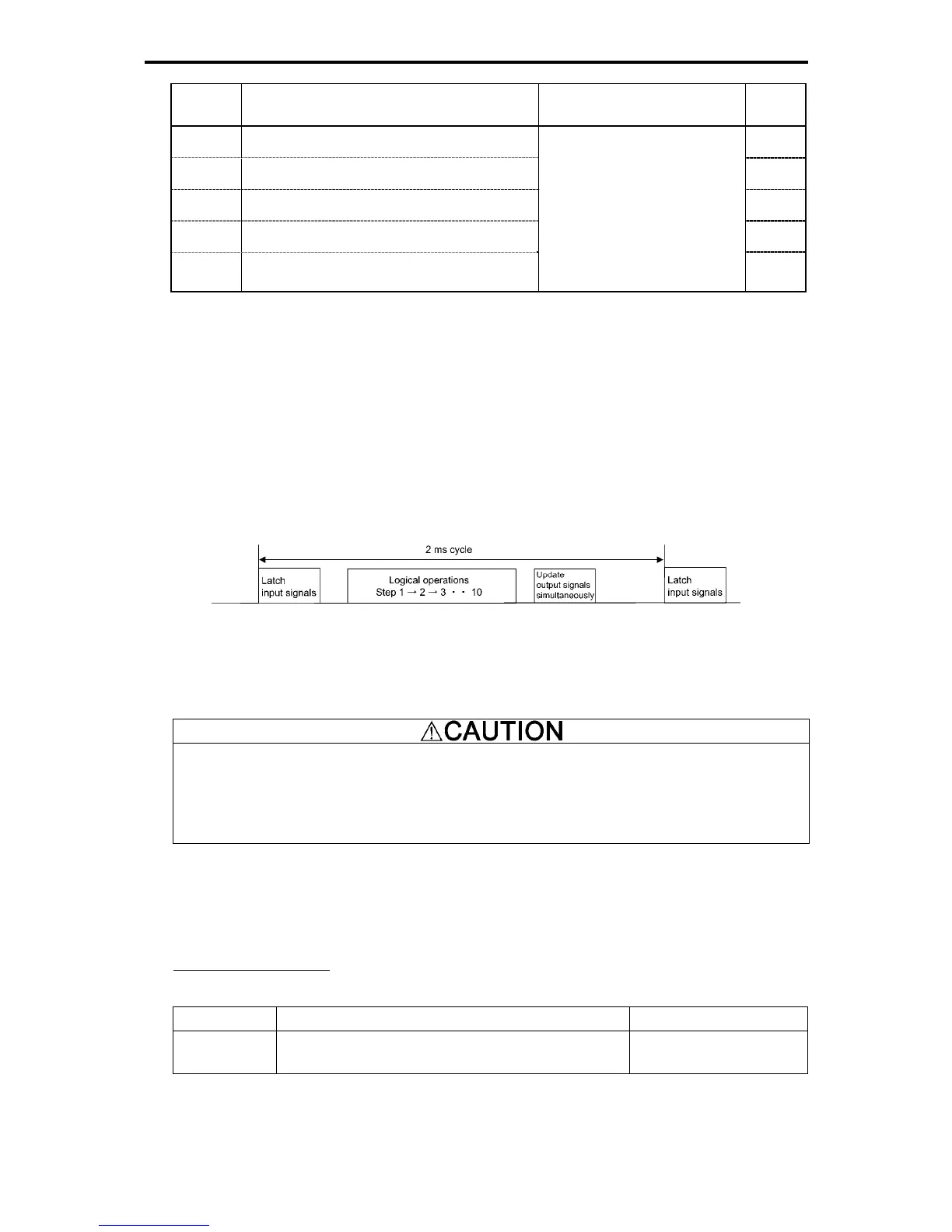
Notes for using a customizable logic
A customizable logic performs processing every 2 ms in the following sequence.
(1) At the beginning of the process, latch the external input signals to all customizable logics in step 1 to 10
to ensure simultaneity.
(2) Logical operations are performed in an order of steps 1 to 10.
(3) In case the output of one step becomes the input of the next step, the step output, of which output is
highly prioritized, can be used in the same process.
(4) The customizable logic updates all of the five output signals simultaneously.
Fig. 5.4-128
When configuring the logic circuit, be sure to consider the processing order of the customizable logic.
Otherwise, signal delay due to slow processing of the logic calculation occurs, causing failure of obtaining
expected output, delayed operation, or output of hazard signals.
When the function code (ex. U code) relating to the customizable logic is changed, or when the
customizable logic cancel signal
CLC is turned on, the operation sequence may change in some settings,
and the operation unexpectedly and suddenly starts, causing danger. Secure sufficient safety before
executing the process.
An accident or injuries could occur.
Customizable logic timer monitor (Step selection) (U91)
To monitor the timer operation status in the customizable logic, the monitor function codes and keypad can
be used.
Selecting the monitor timer
Table 5.4-184
Function Code Function Remarks
U91
1 to 10: Sets the step number of the timer counter is to
be monitored

 Loading...


