5.4 Details of Function Codes
5-260
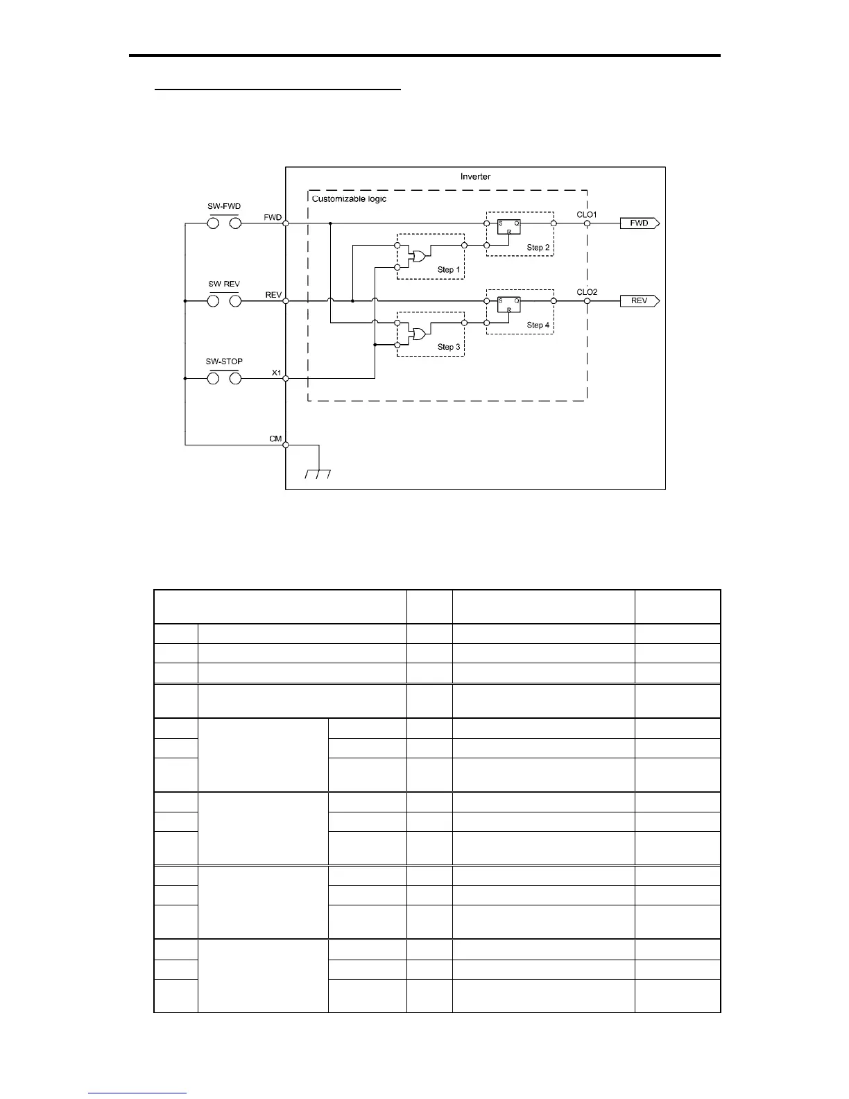
Configuration sample 3: One-shot operation
When starting the inverter by short-circuiting the SW-FWD or SW-REV switch and stopping it by
short-circuiting the SW-STOP switch (which are functionally equivalent to depression of the RUN and STOP
keys on the keypad, respectively), the external circuit, which was conventionally necessary, can be replaced
to the customizable logic.
Fig. 5.4-131
To configure the above customizable logic, set function codes as follows. (Timer selection) and (Time
setting) require no modification unless otherwise required.
Table 5.4-190
Function Code
Setting
Data
Setting Contents Remarks
E01 Terminal X1 (Function selection) 100 No function NONE
E98 Terminal FWD (Function selection) 100 No function NONE
E99 Terminal REV (Function selection) 100 No function NONE
U00 Customizable logic (Operation
selection)
1 Enable
U01 (Input 1) 4011 REV terminal input signal REV
U02 (Input 2) 4001 X1 terminal input signal X1
U03
Customizable logic:
Step 1
(Logic circuit) 3 ORing + General-purpose timer Operation
selection
U06 (Input 1) 4010 FWD terminal input signal FWD
U07 (Input 2) 2001 Output of step 1 SO01
U08
Customizable logic:
Step 2
(Logic circuit) 6 Reset priority flip-flop +
General-purpose timer
Operation
selection
U11 (Input 1) 4010 FWD terminal input signal FWD
U12 (Input 2) 4001 X1 terminal input signal X1
U13
Customizable logic:
Step 3
(Logic circuit) 3 ORing + General-purpose timer Operation
selection
U16 (Input 1) 4011 REV terminal input signal REV
U17 (Input 2) 2003 Output of step 3 SO03
U18
Customizable logic:
Step 4
(Logic circuit) 6 Reset priority flip-flop +
General-purpose timer
Operation
selection

 Loading...


