5.4 Details of Function Codes
5-259
Chapter 5 Function Code
Details of
Function Codes
F codes
E codes
C codes
P codes
H codes
A codes
b codes
r codes
J codes
d codes
U00 to U91
y codes
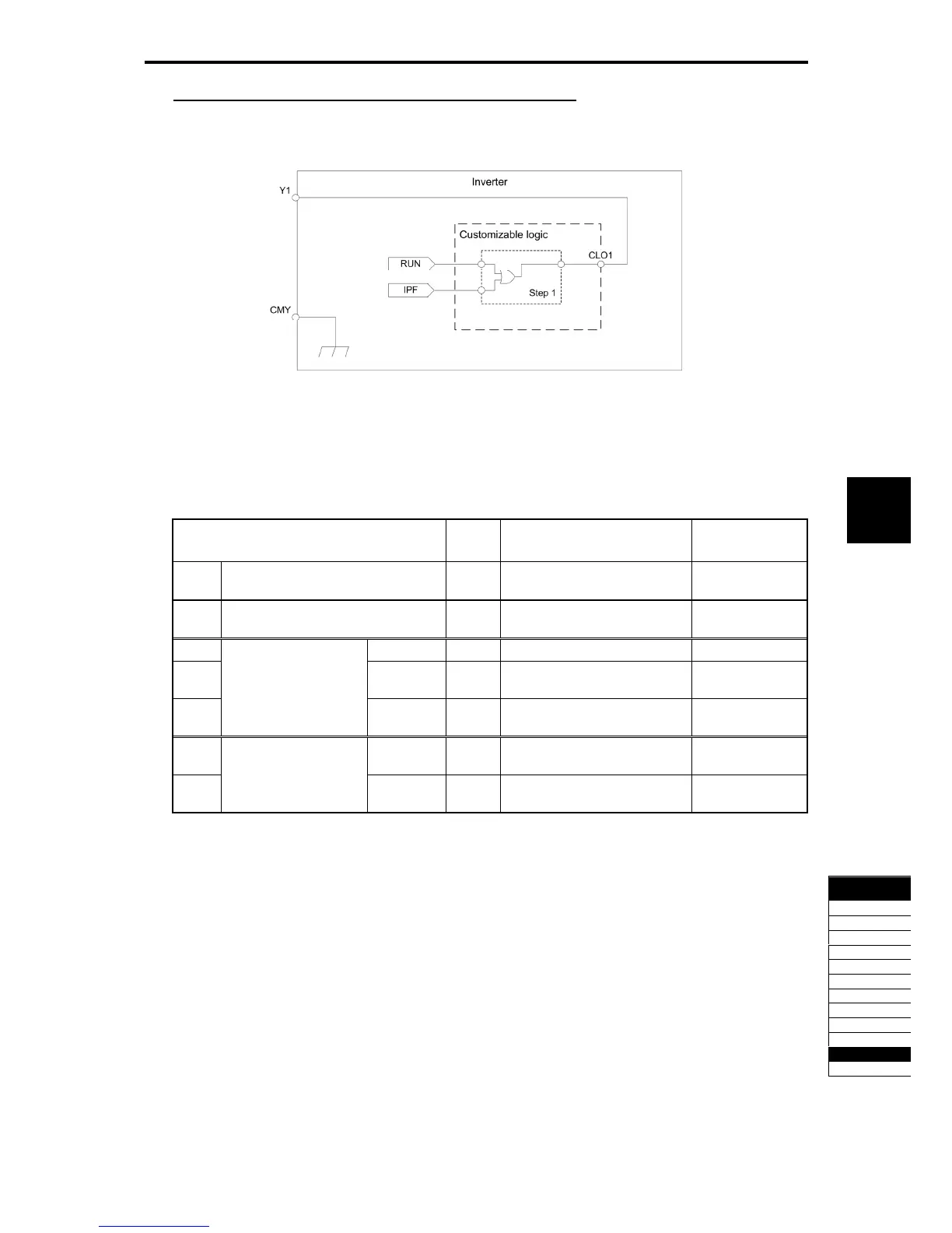
Configuration sample 2: Put two or more output signals into one
When the RUN signal of the general-purpose output is kept on during the restarting from momentary power
failure, replace the external circuit, which was conventionally required, to the customizable logic. In this way,
the using general-purpose output terminals and external relays can be reduced.
Fig. 5.4-130
To configure the above customizable logic, set function codes as listed below. (Timer selection) and (Time
setting) require no modification unless otherwise required.
Table 5.4-189
Function Code Setting
Data
Setting Contents Remarks
E20 Terminal Y1 (Function selection) 111 Customizable logic output
signal 1
CLO1
U00 Customizable logic (Operation
selection)
1 Operation
U01 (Input 1) 0 Running RUN
U02 (Input 2) 6 Auto-restarting after
momentary power failure
IPF
U03
Customizable logic:
Step 1
(Logic
circuit)
3 ORing + General-purpose
timer
Operation
selection
U71 (Output
selection)
1 Output of step 1 SO01
U81
Customizable logic
Output signal 1
(Function
selection)
100 No function
NONE

 Loading...


