5.4 Details of Function Codes
5-270
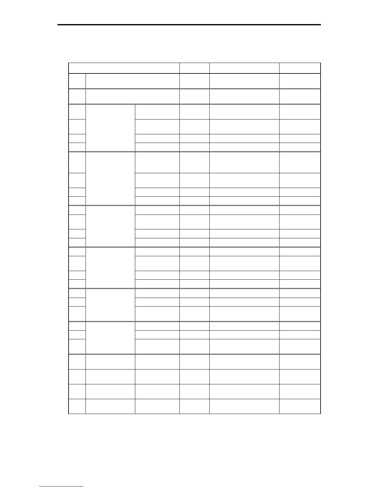
To configure the above customizable logic, set function codes as follows. (Timer selection) and (Time
setting) require no modification unless otherwise required.
Table 5.4-193
Function Code Setting Data Setting Contents Remarks
E98 Terminal FWD (Function selection) 98 Run forward, stop
command
FWD
U00 Customizable logic (Operation
selection)
1 Enable
U01 (Input 1) 4010 FWD terminal input signal
FWD
U03 (Logic circuit) 1 Through output +
General-purpose timer
Operation
selection
U04 (Timer selection) 1 On-delay timer
U05
Customizable logic:
Step 1
(Timer setting) Any value Stage 1 run time
U06 (Input 1) 3001 Output of step 1 (negative
logic)
SO01
U08 (Logic circuit) 8 Falling edge detector +
General-purpose timer
Operation
selection
U09 (Timer selection) 3 Pulse (one-shot)
U10
Customizable logic:
Step 2
(Timer setting) Any value Stage 2 run time
U11 (Input 1) 2002 Output of step 2 SO02
U13 (Logic circuit) 8 Falling edge detector +
General-purpose timer
Operation
selection
U14 (Timer selection) 3 Pulse (one-shot)
U15
Customizable logic:
Step 3
(Timer setting) Any value Stage 3 run time
U16 (Input 1) 2003 Output of step 3 SO03
U18 (Logic circuit) 8 Falling edge detector +
General-purpose timer
Operation
selection
U19 (Timer selection) 3 Pulse (one-shot)
U20
Customizable logic:
Step 4
(Timer setting) Any value Stage 4 run time
U21 (Input 1) 2002 Output of step 2 SO02
U22 (Input 2) 2004 Output of step 4 SO04
U23
Customizable logic:
Step 5
(Logic circuit) 3 ORing + General-purpose
timer
Operation
selection
U26 (Input 1) 2003 Output of step 3 SO03
U27 (Input 2) 2004 Output of step 4 SO04
U28
Customizable logic:
Step 6
(Logic circuit) 3 ORing + General-purpose
timer
Operation
selection
U71 Customizable logic
output signal 1
(Output
selection)
5 Output of step 5 SO05 SS1 command
U72 Customizable logic
output signal 2
5 Output of step 5 SO05 RT1 command
U73 Customizable logic
output signal 3
6 Output of step 6 SO06 SS2 command
U74 Customizable logic
output signal 4
6 Output of step 6 SO06 RT2 command

 Loading...


