5.4 Details of Function Codes
5-273
Chapter 5 Function Code
Details of
Function Codes
F codes
E codes
C codes
P codes
H codes
A codes
b codes
r codes
J codes
d codes
U codes
y01 to y20
Operation selection when error generates (y02, y12)
y02 or y12 specifies the error processing to be performed if an RS-485 communications error occurs.
RS-485 communications errors include logical errors such as address error, parity error, framing error,
transmission protocol error, and physical errors (such as no-response error) specified by y08 and y18). The
inverter can recognize such an error only when it is configured with a run or frequency command sourced
through the RS-485 communications link and it is running. If none of run and frequency commands is
sourced through the RS-485 communications link or the inverter is not running, the inverter does not
recognize any error occurrence.
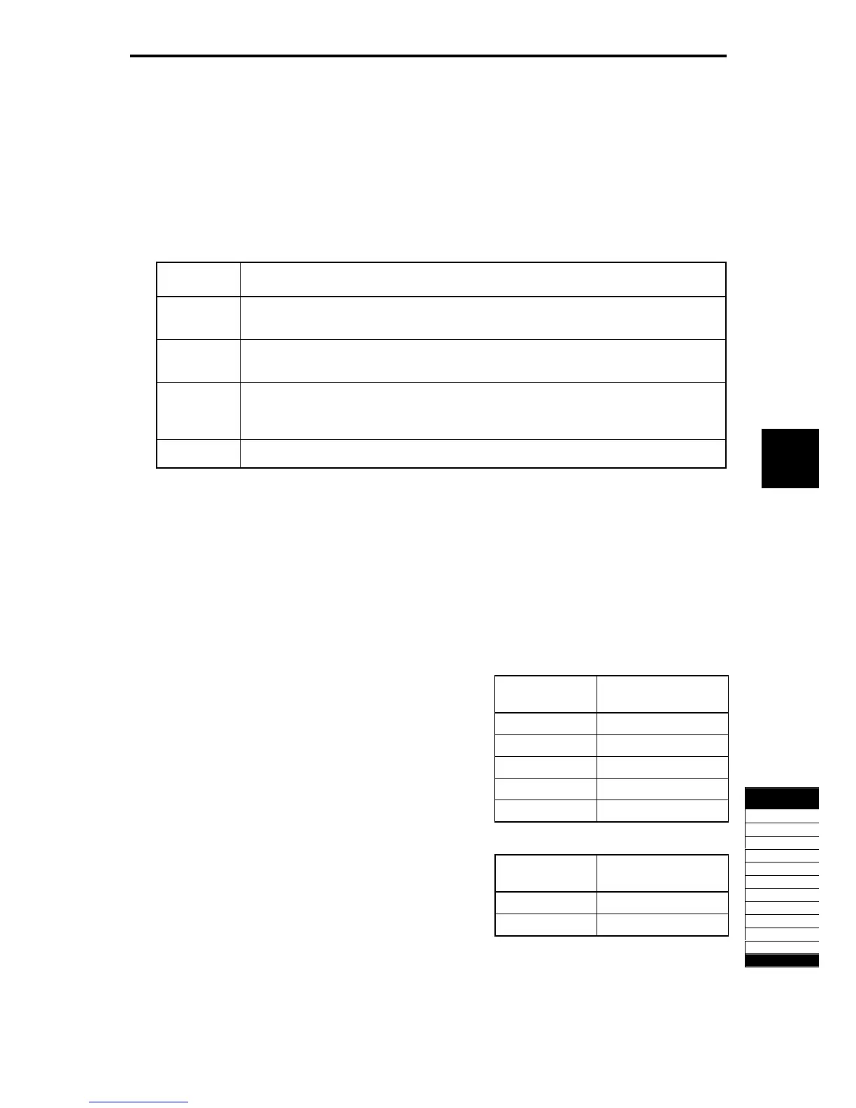
Table 5.4-196
y02, y12
Data
Function
0
Indicates the RS-485 communication error (
er8
for y02 and
erp
for y12) and stops the
operation immediately (alarm stop).
1
Operate for the time set to the error processing timer (y03, y13). Then, output the RS-485
communication error (
er8
for Y02,
erp
for y12) to stop the operation (alarm stop).
2
The communication is retried during the time set to the error processing timer (y03, y13).
If a communications link is recovered, continue operation. Otherwise, display an RS-485
communications error (
er8
for y02 and
erp
for y12) and stop operation (alarm stop).
3
Continues to run even when a communications error occurs.
See the RS-485 Communication User's Manual for details.
Timer operation time (y03, y13)
y03 or y13 specifies an error processing timer. If the timer count has elapsed due to no response from the
other end when a query has been issued, the inverter interprets it as an error occurrence. See the
"No-response error detection time (y08, y18)."
- Data setting range: 0.0 to 60.0 (s)
Baud rate (y04, y14)
Data for y04 and
y14
Function
0 2400 bps
1 4800 bps
2 9600 bps
3 19200 bps
This function sets the baud rate.
- In case of inverter support loader (via RS-485).
Match to the computer setting.
4 38400 bps
Data length selection (y05, y15)
Data for y05 and
y15
Function
0 8 bits
1 7 bits
y05 or y15 specifies the character length.
- In case of inverter support loader (via RS-485):
It automatically becomes 8 bits; therefore, setting is
unnecessary. (The same applies to the Modbus RTU.)

 Loading...


