5.4 Details of Function Codes
5-274
Parity bit selection (y06, y16)
Data for
y06 and
y16
Function
0
No parity bit
(In case of Modbus RTU, stop bit 2 bit)
1
Even parity (1 stop bit for Modbus RTU)
2
Odd parity (1 stop bit for Modbus RTU)
y06 or y16 specifies the parity bit.
- In case of inverter support loader (via
RS-485). It automatically becomes even
number parity; therefore, setting is
unnecessary.
3
No parity bit (1 stop bit for Modbus RTU)
Stop bit selection (y07, y17)
Data for y07 and
y17
Function
0 2 bits
1 1 bit
y07 or y17 specifies the stop bits.
- In case of inverter support loader (via RS-485):
No setting is required since the stop bits automatically
become 1 bit.
In case of Modbus RTU: The stop bit is automatically
determined by interlocking with the parity bit; therefore,
setting is unnecessary.
No-response error detection time (y08, y18)
Data for y08 and
y18
Function
0
No-response is not
detected.
1 to 60
Detection time of 1 to 60
(s)
y08 or y18 detects the status, where no access is received
for a certain amount of time from the equipment, which
always accesses within a specified time to the station, due
to open wire, etc. and sets the time to process the status
as the communication error.
For the communication error handling, see y02 and y12.
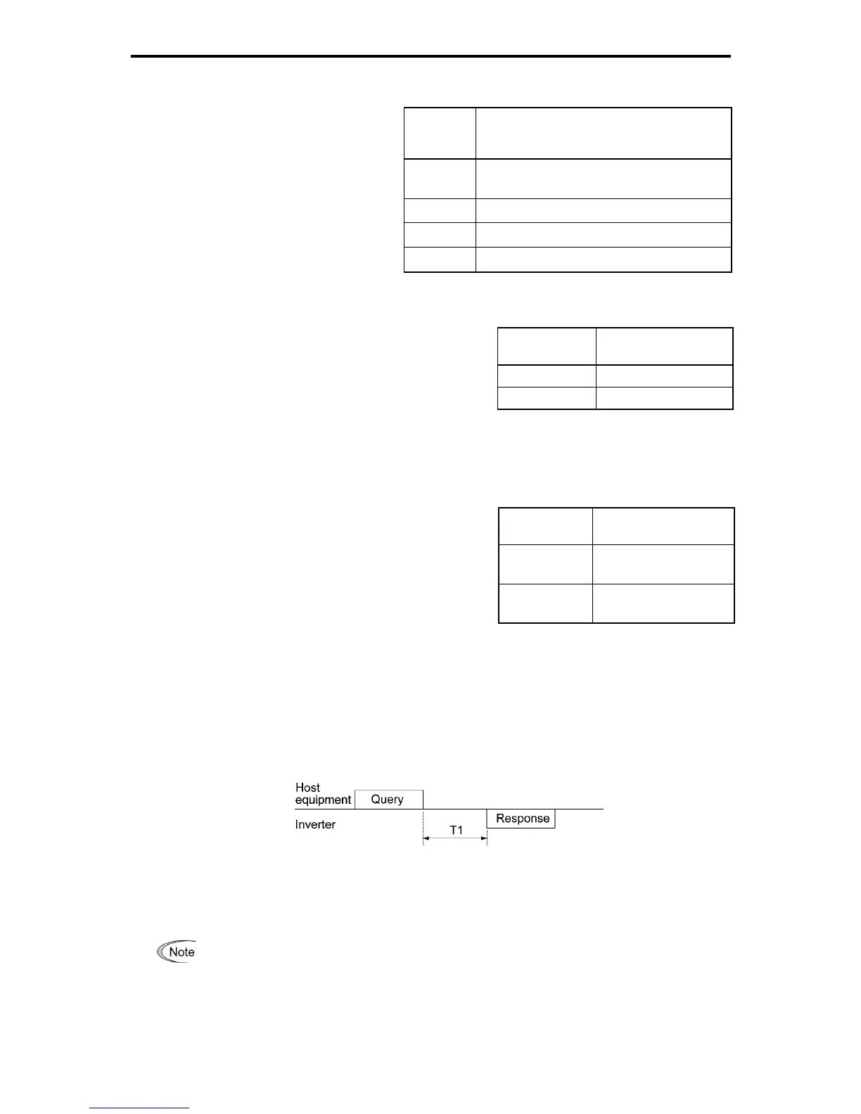
Response interval time (y09, y19)
y09 or y19 specifies the latency time after the end of receiving a query sent from the host equipment (higher
level equipment) such as a computer or PLC until the start of sending the response. This enables the
inverter to control the response timing to match the host equipment that is slow in processing.
- Data setting range: 0.00 to 1.00 (s)
T1 = Response interval + α
α: Processing time inside of the inverter Varies depending on the timing and order.
See the RS-485 Communication User's Manual for details.
When configuring the inverter with FRENIC Loader via the RS-485 communications link, pay
sufficient attention to the performance and configuration of the PC and protocol converter such as
USB-RS-485 converter. (Some protocol converters monitor the communications status and switch
between sending and receiving of transmission data with a timer.)

 Loading...


