10.1 Selecting Motors and Inverters
10-11
Chapter 10 SELECTING OPTIMAL MOTOR AND INVERTER CAPACITIES
(3) For a load running horizontally
Assume a carrier table driven by a motor as shown in Figure 10.1-7. If the table speed is υ (m/s) when the
motor speed is N
M
(r/min), then an equivalent distance from the shaft is equal to 60·υ/(2π·N
M
) (m). The
moment of inertia of the table and load to the shaft is calculated as follows:
(4) For a vertical or inclined lift load
The moment of inertia J (kg·m
2
) of the loads connected with a rope as shown in Figure 10.1-8 and Figure
10.1-9 is calculated with the following equation using the mass of all moving objects, although the motion
directions of those loads are different.
60υ
J=(
2π • N
M
)
2
• (W
O
+ W + W
B
)(kg•m
2
) (10.14)
[2] Calculation of the acceleration time
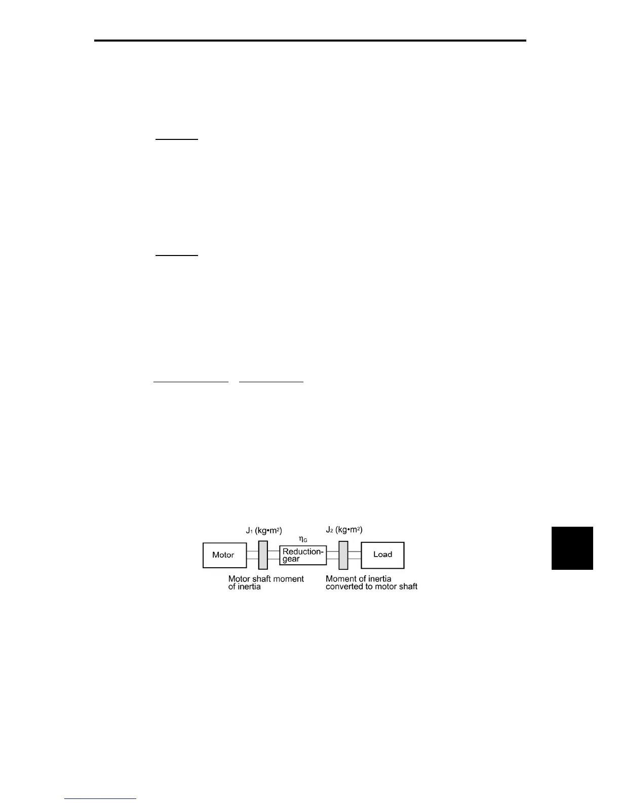
Figure 10.1-11 shows a general load model. Assume that a motor drives a load via a reduction-gear with
efficiency η
G
. The time required to accelerate this load in stop state to a speed of N
M
(r/min) is calculated
with the following equation:
J
1
: Motor shaft moment of inertia (kg·m
2
)
J
2
: Load shaft moment of inertia converted to motor shaft (kg·m
2
)
τ
M
: Minimum motor output torque in driving motor (N·m)
τ
L
: Maximum load torque converted to motor shaft (N·m)
η
G
: Reduction-gear efficiency
As clarified in the above equation, the equivalent moment of inertia becomes (J
1
+J
2
/η
G
) by considering
the reduction-gear efficiency.
Figure 10.1-11 Load Model Including Reduction-gear
60υ
J = (
2π • N
M
)
2
• (W
O
+ W) (kg•m
2
) (10.13)
J
1
+ J
2
/η
G
2π • (N
M
-0)
t
ACC
=
τ
M
- τ
L
/η
G
•
60
(s) (10.15)

 Loading...


