10.4 Selecting a Motor Drive Control
10-20
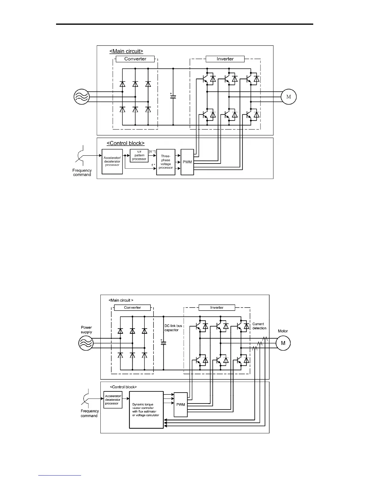
V/f control with slip compensation inactive
Figure 10.4-1 Schematic Block Diagram of V/f Control with Slip Compensation Inactive
As shown in the above configuration of Figure 10.4-1, the inverter does not receive any speed information
feedback from the target machinery being controlled and it controls the load shaft speed only with a
frequency command given by the frequency setting device. The inverter outputs the voltage/frequency
following the V/f pattern processor's output to drive a motor. This control disables all automatically
controlled features such as the slip compensation, so no unpredictable output fluctuation occurs, enabling
stable operation with constant output frequency. This control is suitable for applications that makes the
speed of existing motor variable or do not need quick speed change such as variable torque load
equipment, fans, and pumps.
Dynamic torque vector control
Figure 10.4-2 Schematic Block Diagram of Dynamic Torque Vector Control

 Loading...


