10.4 Selecting a Motor Drive Control
10-23
Chapter 10 SELECTING OPTIMAL MOTOR AND INVERTER CAPACITIES
Vector control with speed sensor
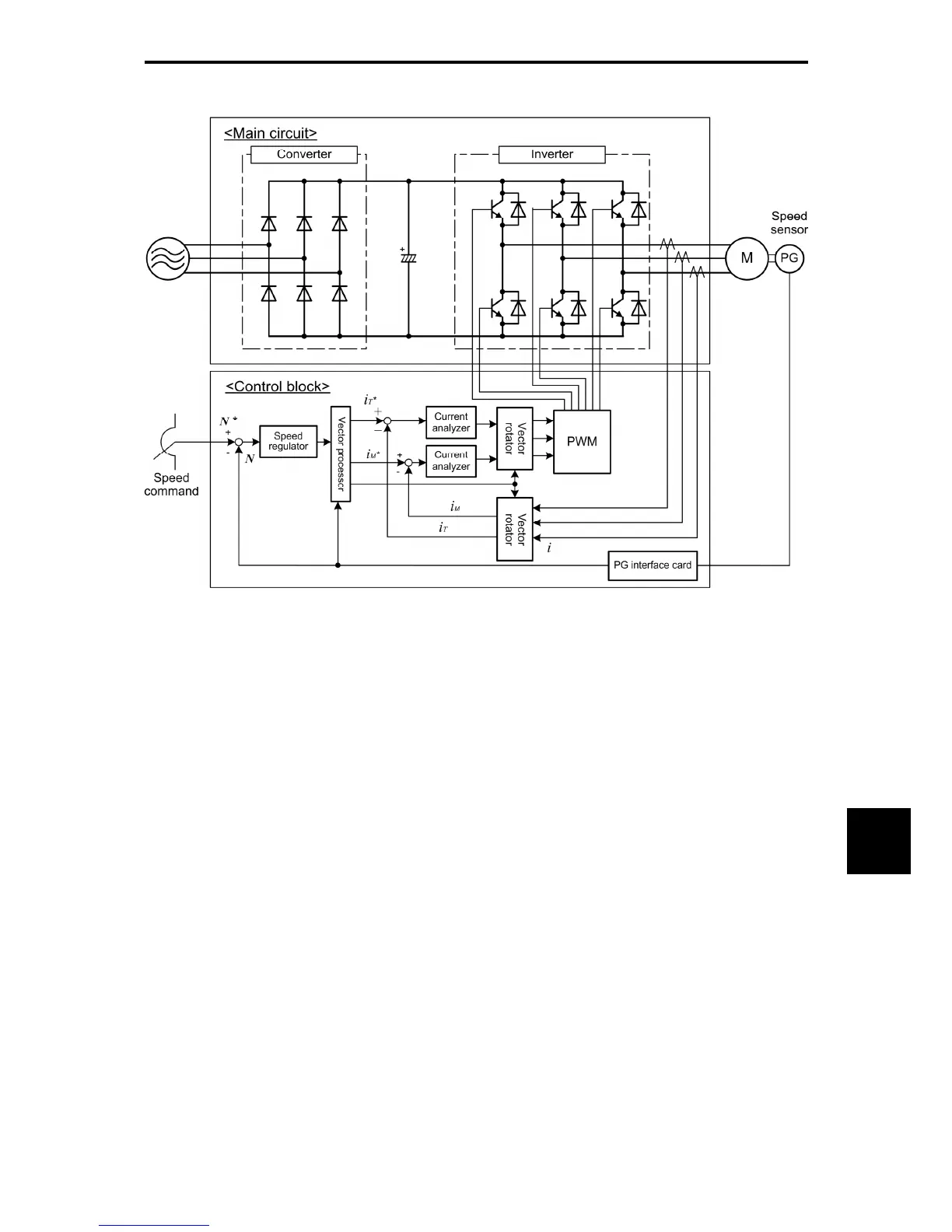
Figure 10.4-5 Schematic Block Diagram of Vector Control with Speed Sensor
As shown in the above configuration, the inverter is equipped with an optional PG (Pulse Generator)
interface card and receives the feedback signals from the PG to detect the motor rotational position and
speed. This enables rapid-response control of the motor speed with high accuracy. (It is recommended to
use Fuji motors exclusively designed for vector control.)
By dividing the current flowing across the motor into the exciting current and torque current to control them
separately, the inverter can control an induction motor with as high controllability as a DC motor. This
control is suitable for:
• Applications that need to minimize the speed fluctuation over quick load variations
• Applications that need highly precise positioning
• Applications that need the servo-lock function to generate a holding torque negating external
disturbances even while the motor is stopping
• Applications that need large torque output in low speed operation
• Applications that need to protect the equipment from an unexpectedly outputted large torque, because
the torque limiting/controlling function is available

 Loading...


