10.4 Selecting a Motor Drive Control
10-22
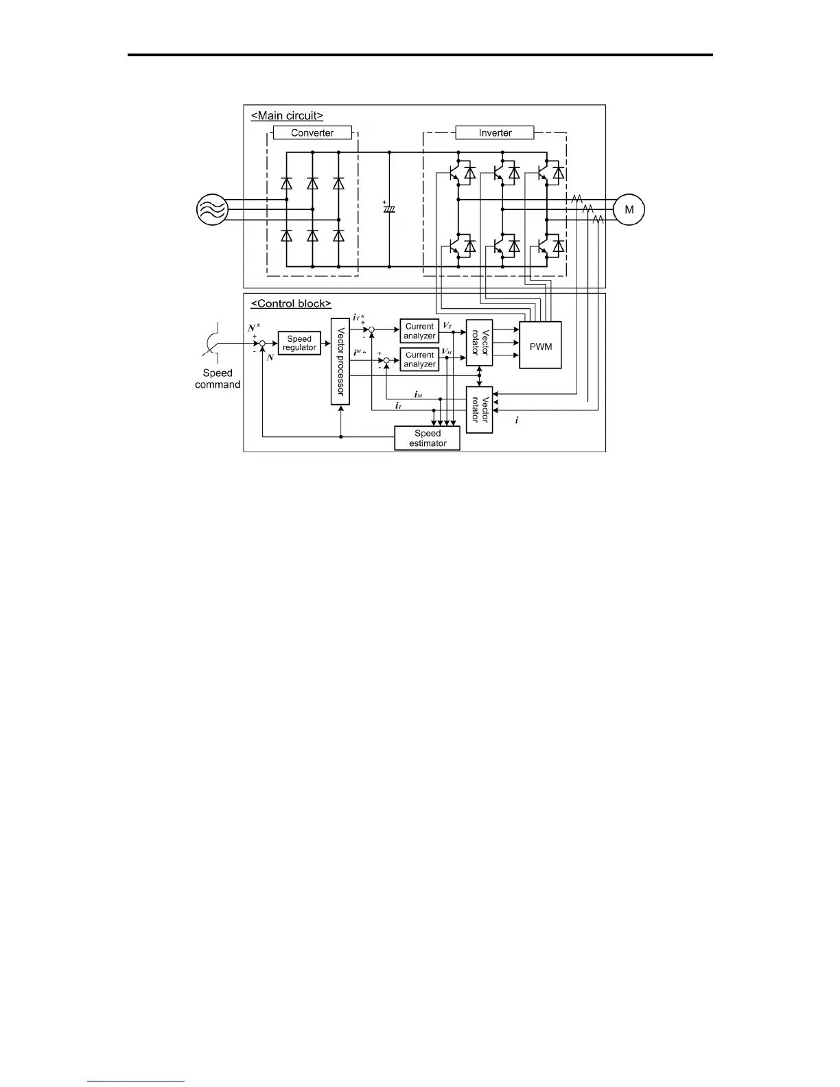
Vector control without speed sensor
Figure 10.4-4 Schematic Block Diagram of Vector Control without Speed Sensor
This control estimates the motor speed based on the inverter's output voltage and current to use the
estimated speed for speed control. It also decomposes the motor drive current into the exciting and torque
current components, and controls each of those components in vector. No PG (pulse generator) interface
card is required. It is possible to obtain the desired response by adjusting the control constants (PI
constants) using the speed regulator (PI controller).
The vector control without speed sensor in the FRENIC-MEGA series has adopted the magnetic flux
observer system, improving the control performance in the low speed domain.
Since this control controls the motor current, it is necessary to secure some voltage margin between the
voltage that the inverter can output and the induced voltage of the motor, by keeping the former lower than
the latter. Usually a general-purpose motor is so designed that the voltage matches the commercial power.
Under the control, therefore, it is necessary to suppress the motor terminal voltage to the lower level in
order to secure the voltage margin required. However, driving the motor with the motor terminal voltage
suppressed to the lower level cannot generate the rated torque even if the rated current originally specified
for the motor is applied. To ensure the rated torque, it is necessary to increase the rated current. (This also
applies to vector control with speed sensor.)
The control is not available in MD-mode inverters, so do not set F42 data to "5" for those inverters.

 Loading...


