11.4 Option
11-48
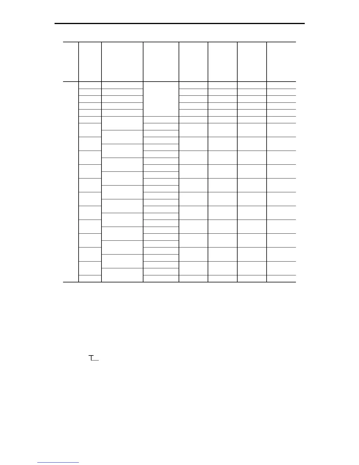
Table 11.4-21 DC Reactor (DCR)
Power supply
voltage
Nominal
applied
motor
(kW)
Inverter type Mode
DC reactor
type
Rated
current (A)
Inductance
(mH)
Generated
loss (W)
0.4 FRN0.4G1-2J DCR2-0.4 3 12 1.9
0.75 FRN0.75G1-2J DCR2-0.75 5 7 2.8
1.5 FRN1.5G1-2J DCR2-1.5 8 4 4.6
2.2 FRN2.2G1-2J DCR2-2.2 11 3 6.7
3.7 FRN3.7G1-2J
HD
DCR2-3.7 18 1.7 8.8
5.5 HD DCR2-5.5 25 1.2 14
FRN5.5G1-2J
LD
7.5
HD
DCR2-7.5 34 0.8 16
FRN7.5G1-2J
LD
11
HD
DCR2-11 50 0.6 27
FRN11G1-2J
LD
15
HD
DCR2-15 67 0.4 27
FRN15G1-2J
LD
18.5
HD
DCR2-18.5 81 0.35 29
FRN18.5G1-2J
LD
22
HD
DCR2-22A 98 0.3 38
FRN22G1-2J
LD
30
HD
DCR2-30B 136 0.23 37
FRN30G1-2J
LD
37
HD
DCR2-37B/
DCR2-37C
167/
175
0.19/
0.119
47/
63
FRN37G1-2J
LD
45
HD
DCR2-45B/
DCR2-45C
203/
213
0.16/
0.1
52/
68
FRN45G1-2J
LD
55
HD
DCR2-55B/
DCR2-55C
244/
256
0.13/
0.08
55/
75
FRN55G1-2J
LD
75
HD
DCR2-75C 358 0.05 96
FRN75G1-2J
LD
90
HD
DCR2-90C 431 0.042 100
Three-phase
200 V
110
FRN90G1-2J
LD DCR2-110C 552 0.034 126
(Note 1) Generated losses listed in the above table are approximate values that are calculated according
to the following conditions:
• The power supply is three-phase 200 V/400 V, 50 Hz with 0% interphase voltage unbalance
ratio.
• The power supply capacity uses the larger value of either 500 kVA or 10 times the rated
capacity of the inverter.
• The motor is a 4-pole standard model at full load (100%).
• An AC reactor (ACR) is not connected.
(Note 2) A box () in the above table replaces an alphabetic letter depending on the enclosure.
S (Basic type), E (EMC filter built-in type)

 Loading...


