11.4 Option
11-70
Terminal functions
Table 11.4-36
Terminal
Signal
Name Specifications
[PI]
External power input
terminal *1
Power input terminal from the external device for PG
+12 VDC±10% input, or
+15 VDC±10% input
(Use the power source 150 mA or above which is larger
than the PG current consumption.)
[PO] Power output terminal *2
Power output terminal for PG
+12 VDC±10%/120 mA output, or
+15 VDC±10%/120 mA output
[CM] Common output
Common terminal for power supply to PG
(Equipotent with the inverter's terminal [CM])
[XA]
Command input terminal
for A-phase pulse train
Input terminal for A-phase signal of command pulse train
[XB]
Command input terminal
for B-phase pulse train
Input terminal for B-phase signal of command pulse train
[XZ] ― (Not used.)
[YA]
Feedback input terminal for
A-phase pulse train
Input terminal for A-phase signal of pulse train fed back
from PG
[YB]
Feedback input terminal for
B-phase pulse train
Input terminal for B-phase signal of pulse train fed back
from PG
[YZ]
Feedback input terminal for
Z-phase pulse train
Input terminal for Z-phase signal of pulse train fed back
from PG
*1
Use an external power source if the PG current consumption exceeds 120 mA.
*2
Turn the internal switch to the proper position according to the voltage specification of PG power.
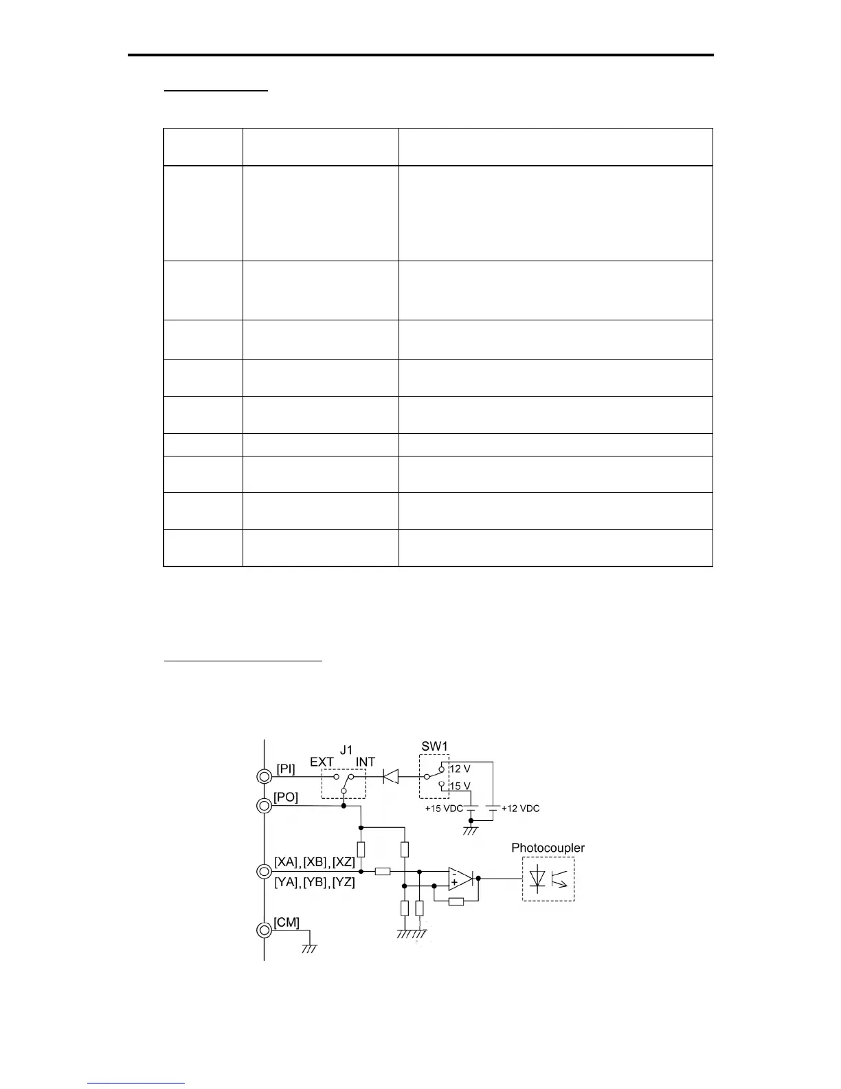
Internal circuit configuration
Figure 11.4-29 shows the internal circuit configuration of the optional PG interface card. This figure is an
example of supplying the PG power from the internal +12 VDC source.
Figure 11.4-29 Internal Circuit Configuration

 Loading...


