11.4 Option
11-82
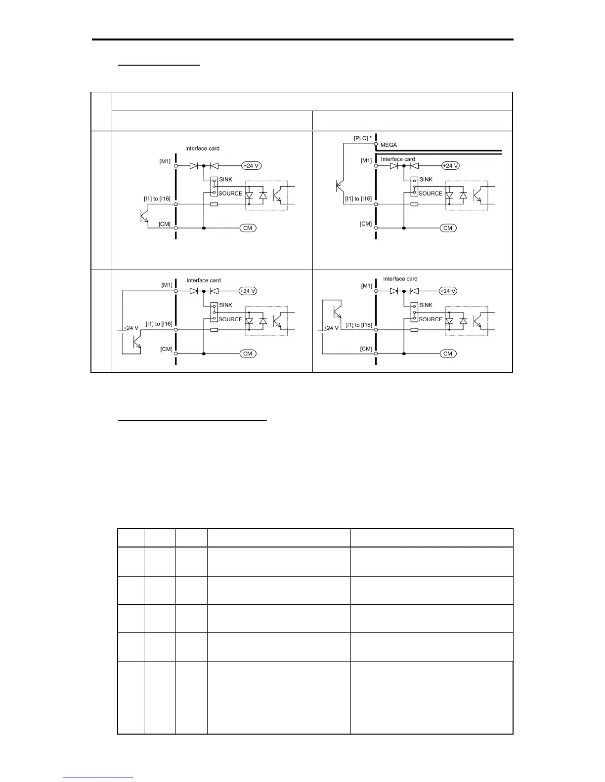
Connection example
Table 11.4-53
Connection example
Power
supply
SINK mode SOURCE mode
Internal
* The maximum allowable current for terminal
[PLC] on the FRENIC-MEGA is 100 mA.
External
Configuring inverter's function codes
To enable frequency command inputs from this interface card, it is necessary to set function code F01
(Frequency Command 1) or C30 (Frequency Command 2) to "11" (Digital input interface card). Also
specify the polarity and input mode of the frequency command by using function codes o19 (DI polarity)
and o20 (DI mode), respectively.
Turning the terminal input OFF or ON sets each bit data to "0" or "1," respectively.
Table 11.4-54
No. o19 o20 Input signal name
Terminal function and configuration details
1) 0 0 8-bit binary frequency command
Setting resolution = Maximum output
frequency (1/255)
2) 0 1 12-bit binary frequency command
Setting resolution = Maximum output
frequency (1/4095)
3) 0 2 15-bit binary frequency command
Setting resolution = Maximum output
frequency (1/32767)
4) 0 3 16-bit binary frequency command
Setting resolution = Maximum output
frequency (1/65535)
5) 0,1 4
4-digit BCD
frequency command
(0 to 99.99 Hz)
Frequency can be specified within the
range of 0 to 99.99 Hz (Setting
resolution = 0.01 Hz).
If a frequency command exceeding the
maximum output frequency is input, the
maximum output frequency applies.

 Loading...


