11.4 Option
11-87
Chapter 11 SELECTING PERIPHERAL EQUIPMENT
Class
Terminal
Signal
Name Explanation Remarks
[Ao+]
Voltage output
(+)
• Outputs the monitor signal of analog DC
voltage (0 to ±10 VDC)
• One of the followings can be issued from this
terminal.
• Output frequency (before slip compensation,
after slip compensation)
• Output current • Output voltage
• Output torque
• Load factor •Input power
• PID feedback value
• PG feedback value
• DC link bus voltage
• Universal AO • Motor output
• Analog output test • PID command
• PID output
• Resolution: 1/3000
* Capable of driving up to two analog voltmeters
with 10 kΩ input impedance.
[Ao-]
Analog voltage
output -
• Reference terminal for analog voltage output
+[Ao+]
Equipotent with
the inverter's
terminal [11]
[CS+]
Analog current
output +
• Outputs the monitor signal of analog DC
current (4 to 20 mA DC)
• One of the followings can be issued from this
terminal.
• Output frequency (before slip compensation,
after slip compensation)
• Output current
• Output voltage
• Output torque
• Load factor
• Input power
• PID feedback value
• PG feedback value
• DC link bus voltage
• Universal AO
• Motor output
• Analog output test
• PID command
• PID output
• Resolution: 1/3000
* Input impedance of the external device: Max.
500 Ω
Isolated from
terminals [31],
[Ao-], and [11]
(the inverter’s
terminals)
Analog output
[CS-]
Analog current
output -
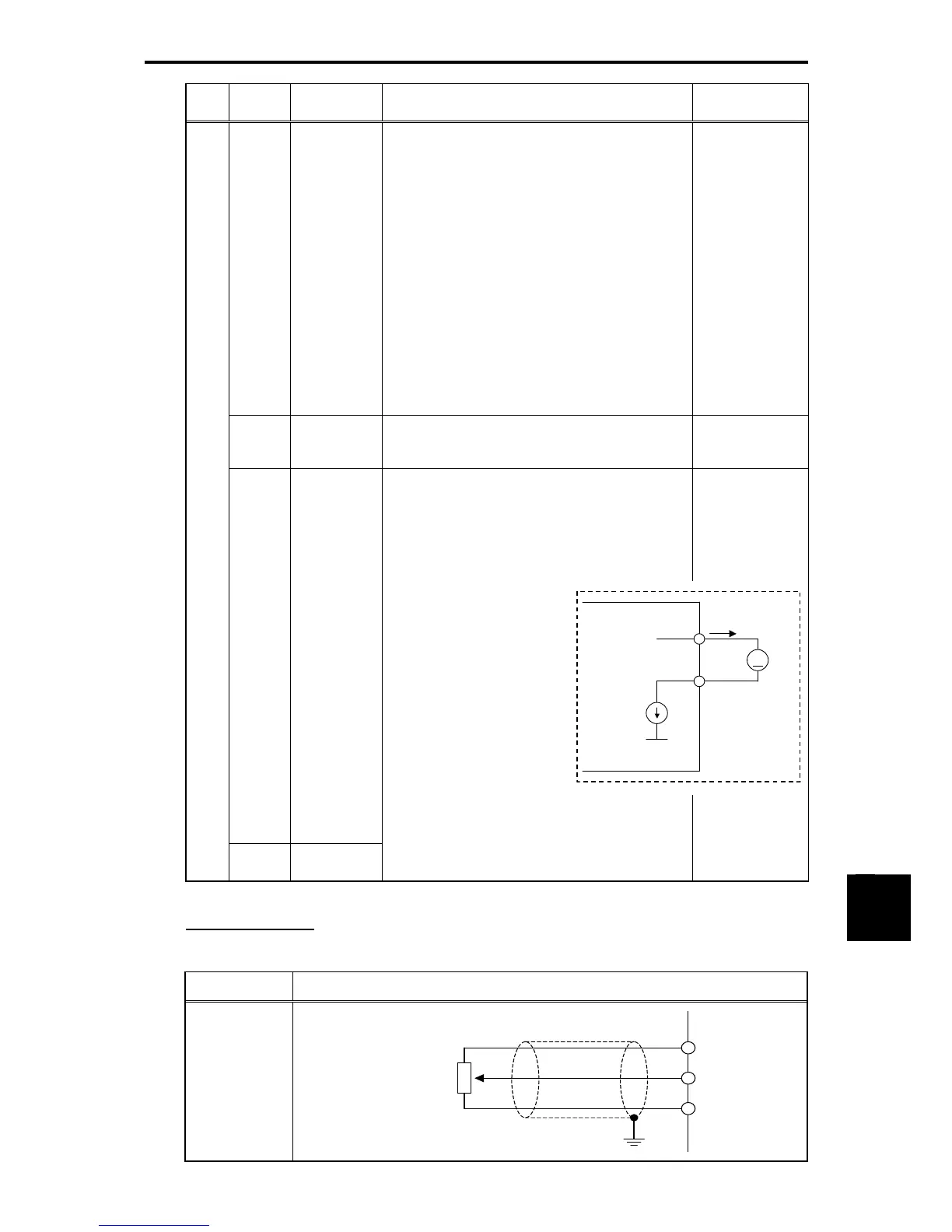
Connection example
Table 11.4-60
Terminal Signal Connection method
[32]
Shielded wire
[P10]
[32]
[31]
Potentiometer
1k to 5k
Ω
24 VDC
[CS+]
[CS-]
[CM]
([CM] on the inverter)
Current
source
A
Ammeter
<Control circuit>
Current

 Loading...


