11.4 Option
11-97
Chapter 11 SELECTING PERIPHERAL EQUIPMENT
Area occupied in MICREX-SX and data allocation address
Standard Format
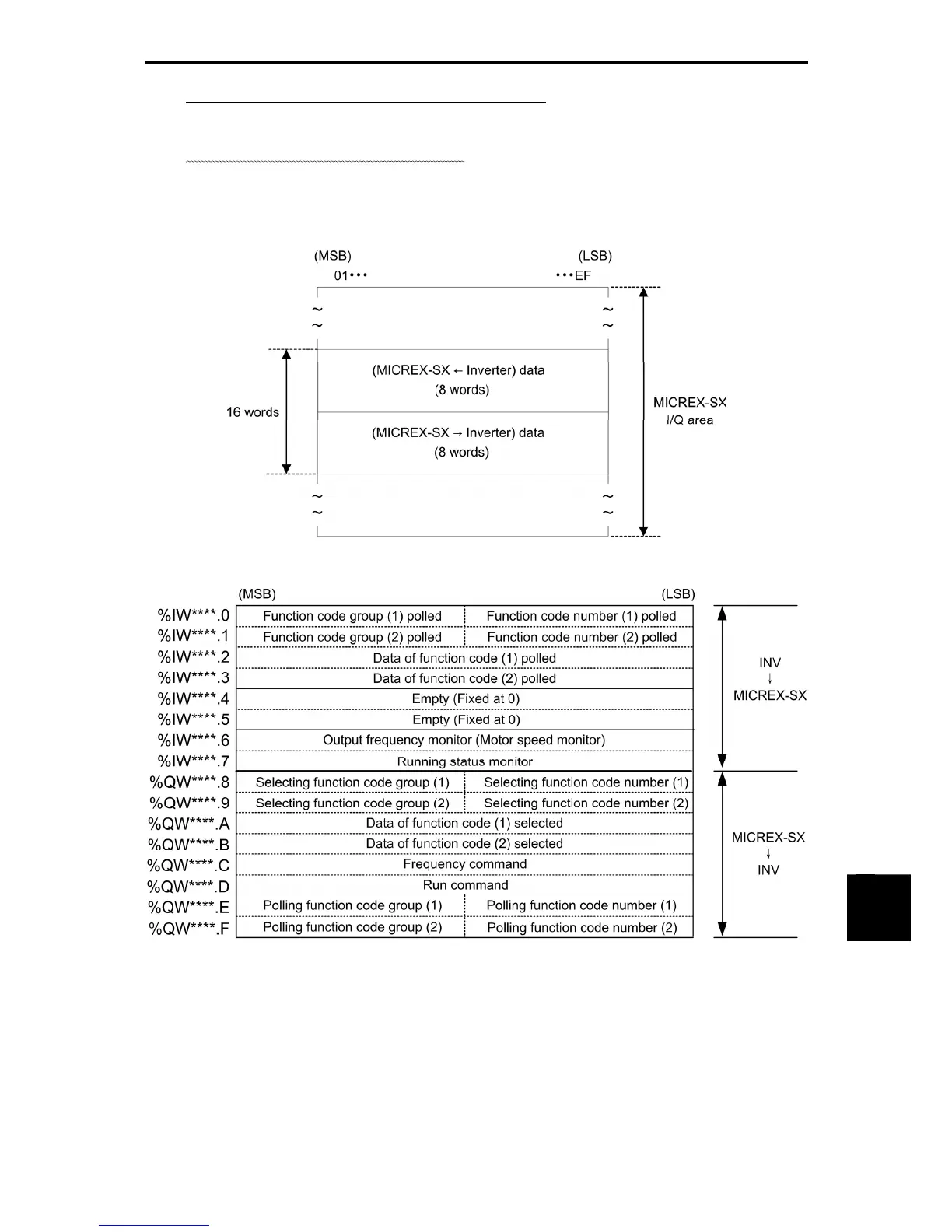
When the standard format is selected (o30 = 0),
SX-bus communication uses a 16-word area per inverter
in the MICREX-SX I/O area as shown below. (A maximum of 10 inverters can be connected.) The lower
8-word area is used as a status area for reading out data from the inverter to the MICREX-SX, the upper
8-word one, as a control area for writing data from the MICREX-SX to the inverter.
Figure 11.4-37
Note: Asterisks (****) denote a SX bus station address configured by the RSW1 and RSW2.
Figure 11.4-38

 Loading...


