11.4 Option
11-105
Chapter 11 SELECTING PERIPHERAL EQUIPMENT
DIP switch configuration
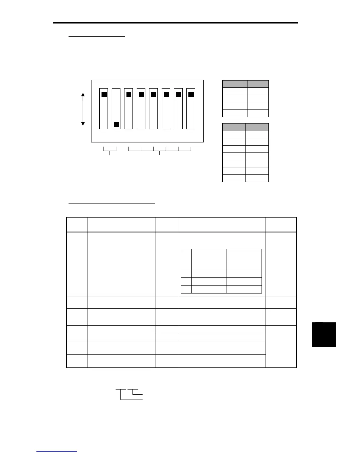
The DIP switch specifies the communication data rate and the node address as shown below. It offers a
choice of data rates (125, 250, and 500 kbps) and a choice of node address ranging from 0 to 63. The DIP
switch should be configured before the inverter and the communications card are turned ON. If the switch
is configured when they are turned ON, the new configuration does not go into effect until they are
restarted.
Figure 11.4-39 DIP Switch Configuration (showing an example of Data Rate = 500 kbps and Node Address = 63)
Configuring inverter's function codes
Table 11.4-80
Function
code
Description
Factory
default
Function Remarks
y98
Select run/frequency
command sources
0 Select from the following choices:
Table 11.4-81
y98 Frequency
command source
Run command
source
0 Inverter Inverter
1 DeviceNet Inverter
2 Inverter DeviceNet
3 DeviceNet DeviceNet
o27
Select error processing for
DeviceNet breaks
0
Refer to the instruction manual of the
DeviceNet communications card.
o28
Set the operation timer to be
used in error processing for
network breaks
0.0s
0.0 to 60.0 s
o31
Select output instance
0
Refer to 11.4-83.
o32
Select input instance
0
Refer to 11.4-83.
o40 to
43
Assign the function code
writing data, 1 to 4
0000
See Note below.
o48 to
51
Assign the function code
reading data, 1 to 4
0000
See Note below.
Restart the
inverter to
validate
the new
settings.
Note: Configuring inverter’s function codes o40 to o43 and o48 to o51
Specify the function code group (Table 11.4-82) and number in a 4-digit hexadecimal notation.
□□□□
Function code number (hexadecimal)
Function code group (in accordance with Table 4.25)
Figure 11.4-40
1 2 3 4 5 6 7 8
Data rate (DR) Node address (NA)
ON
OFF
DR DIP 1-2
125 kbps 00
250 kbps 01
500 kbps 10
Prohibited 11
NA DIP 3-8
0 000000
1 000001
2 000010
3 000011
… …
62 111110
63 111111

 Loading...


