12.4 Common Specifications
12-13
Chapter 12 SPECIFICATIONS
Table 12.4-3
Item Explanation Remarks
Frequency limiter
(Upper limit and lower limit
frequencies)
• Specifies the upper and lower limits in Hz.
• It is possible to choose the operation to be performed when the reference frequency drops below
the lower limit specified by F16. (Holding the output frequency at the low level specified by
F16/decelerating the motor to a stop)
Bias Frequency Bias of set frequency and PID command can be independently set (setting range: 0 to ±100%).
Analog input
• Gain: Set in the range from 0 to 200%
• Off-set: Set in the range from -5.0 to +5.0%
• Filter: Set in the range from 0.00 to 5.00 s
Jump frequency Three operation points and their common jump width (0 to 30.0 Hz) can be set.
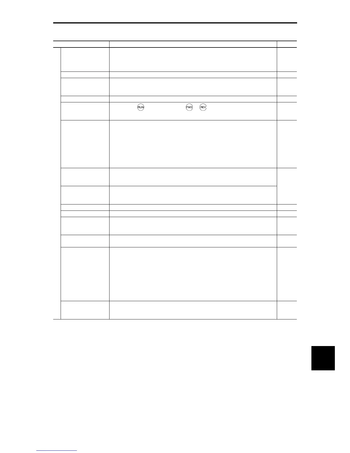
Jogging operation
Operation with
key (standard keypad), or key (multi-function keypad), or digital
contact input FWD or REV (Exclusive acceleration/deceleration time setting, exclusive frequency
setting)
Auto-restart after
momentary power failure
• Trip at power failure: The inverter trips immediately after power failure.
• Trip at power recovery: Coast-to-stop at power failure and trip at power recovery
• Deceleration stop: Deceleration stop at power failure, and trip after stoppage
• Continue to run: Operation is continued using the load inertia energy.
• Start at the frequency selected before momentary power failure: Coast-to-stop at power failure
and start after power recovery at the frequency selected before momentary stop. *1 to *3
• Start at starting frequency: Coast-to-stop at power failure and start at the starting frequency after
power recovery. *1 to *3
Hardware current limiter
Limits the current by hardware to prevent an overcurrent trip from being caused by fast load
variation or momentary power failure, which cannot be covered by the software current limiter.
This limiter can be canceled.
Operation by commercial
power supply
• With commercial power selection command, the inverter outputs 50/60 Hz (SW50, SW60). *1 to
*3
• The inverter has the commercial power supply selection sequence.
Slip compensation *2, *3 Compensates for decrease in speed according to the load.
Droop control Decreases the speed according to the load torque.
Torque limit
• Switchable between 1st and 2nd torque limit values
• Torque limit, torque current limit, and power limit are set for each quadrant. *6, *7
• Analog torque limit input
*9
Software current limiter
Automatically reduces the frequency so that the output current becomes lower than the preset
operation level. *1 to *5
PID control
• PID processor for process control/dancer control
• Normal operation/inverse operation
• Low liquid level stop function (pressurized operation possible before low liquid level stop)
• PID command: Keypad, analog input (from terminals [12], [C1] and [V2]), RS-485 communication
• PID feedback value: Analog input (from terminals [12], [C1] and [V2])
• Alarm output (absolute value alarm, deviation alarm)
• PID output limiter
• Integration reset/hold
• Anti-reset wind-up function
Control
Auto search for idling
motor speed *1 to *3 and
*6
The inverter automatically searches for the idling motor speed to be harmonized and starts to drive
it without stopping it.
(Motor constants need tuning: Auto-tuning (offline))
*1 Available under V/f control.
*2 Available under dynamic torque vector control.
*3 Available when the slip compensation is made active under V/f control.
*4 Available under V/f control with speed sensor. (PG option required)
*5 Available under dynamic torque vector control with speed sensor. (PG option required)
*6 Available under vector control without speed sensor.
*7 Available under vector control with speed sensor. (PG option required)
*9 Available in inverters having a ROM version 1000 or later.

 Loading...


