12.4 Common Specifications
12-14
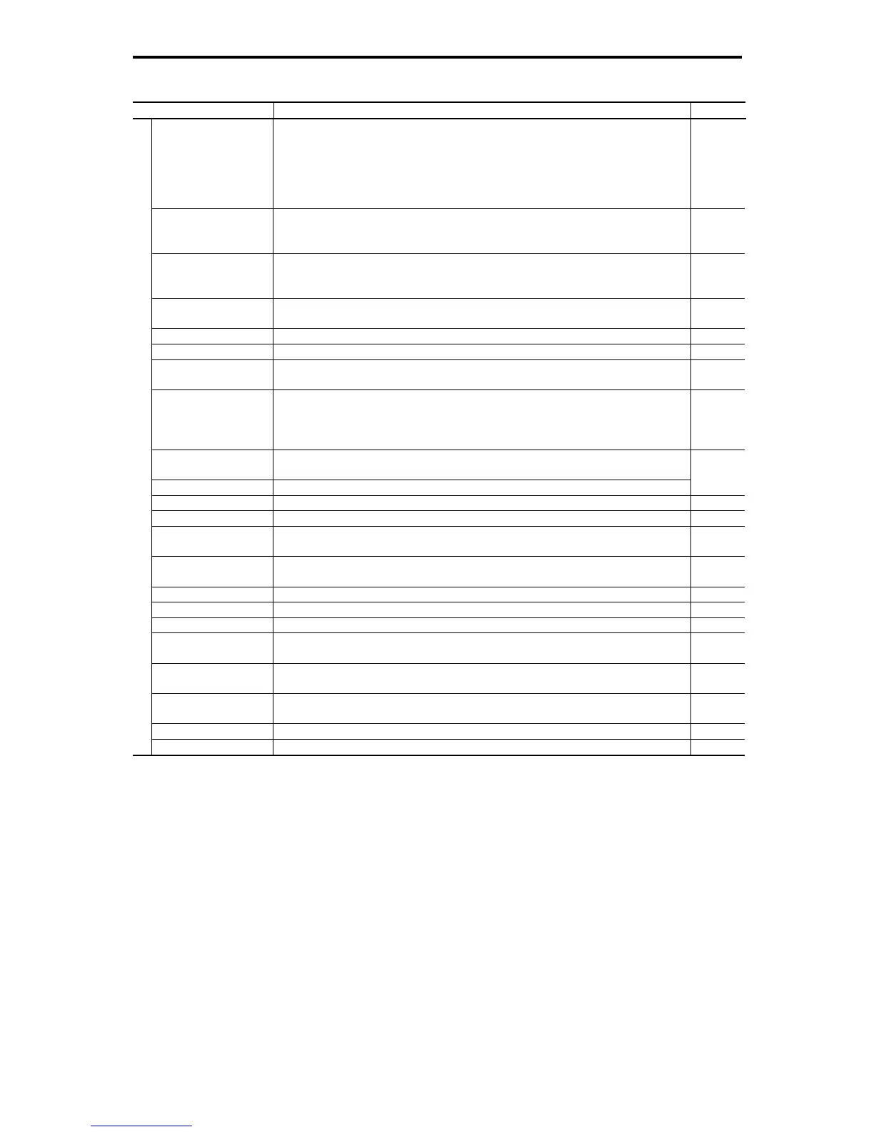
Table 12.4-4
Item Explanation Remarks
Anti-regenerative control
(Automatic deceleration)
• If the DC link bus voltage or calculated torque exceeds the automatic deceleration level during
deceleration, the inverter automatically prolongs the deceleration time to avoid overvoltage trip.
(It is possible to select forcible deceleration actuated when the deceleration time becomes three
times longer.)
• If the calculated torque exceeds automatic deceleration level during constant speed operation,
the inverter avoids overvoltage trip by increasing the frequency.
Deceleration characteristic
(improved braking
capacity)
The motor loss is increased during deceleration to reduce the regenerative energy in the inverter
to avoid overvoltage trip.
Auto energy saving
operation
The output voltage is controlled to minimize the total sum of the motor loss and inverter loss at a
constant speed. (With digital input signal, auto energy saving mode can be turned ON or OFF by
an external device.)
Overload prevention
control
If the surrounding temperature or IGBT joint temperature increases due to overload, the inverter
lowers the output frequency to avoid overload.
Auto-tuning (offline) Tuning the motor while the motor is stopped or running, for setting up motor parameters.
Onine tuning *2, *3 Compensates for the change of motor parameters caused by temperature rise. *10
Cooling fan ON/OFF
control
• Detects inverter internal temperature and stops cooling fan when the temperature is low.
• The fan control signal can be output to an external device.
2nd to 4th motor settings
• Switchable among the four motors
• Code data for four kinds of specific functions can be switched (even during operation).
It is possible to set the base frequency, rated current, torque boost, and electronic thermal slip
compensation as the data for 1st to 4th motors.
Universal DI
The status of external digital signal connected with the universal digital input terminal is transferred
to the host controller.
Universal DO Digital command signal from the host controller is output to the universal digital output terminal.
Universal AO The analog command signal from the host controller is output to the analog output terminal.
Speed control *7 Notch filter for vibration suppression *9
Constant peripheral speed
control *4, *5
Controls the rotating speed to keep the peripheral speed (line speed) constant so that an increase
in the peripheral speed is suppressed.
*10
Synchronous operation *4,
*5, *7
Synchronizes the positioning of two motors.
*10
Pre-excitation *6, *7 Excitation is carried out to create the motor flux before starting the motor.
Zero speed control *7 The motor speed is held to zero by forcibly zeroing the speed command.
Servo lock *7 Stops the motor and holds the motor in the stopped position. *8
Torque control *6, *7
• Analog torque command input
• Speed limit function is provided to prevent the motor from becoming out of control.
*9
Rotational direction
limitation
Select either of reverse or forward rotation prevention.
Dew condensation
prevention
When the motor is stopped, current is automatically supplied to the motor to keep the motor warm
and avoid condensation.
Customized logic interface Available in 10 steps with the functions of 2-input, 1-output, logical operation, and timer function *9
Control
Battery-powered operation Drives the inverter in a low voltage status by the battery power. *11
*1 Available under V/f control.
*2 Available under dynamic torque vector control.
*3 Available when the slip compensation is made active under V/f control.
*4 Available under V/f control with speed sensor. (PG option required)
*5 Available under dynamic torque vector control with speed sensor. (PG option required)
*6 Available under vector control without speed sensor.
*7 Available under vector control with speed sensor. (PG option required)
*8 Available in inverters having a ROM version 0500 or later.
*9 Available in inverters having a ROM version 1000 or later.
*10 Available in inverters having a ROM version 3000 or later.
*11 Available in inverters having a ROM version 3600 or later.

 Loading...


