13.5 Conformity with Low Voltage Directive in Europe
13-13
Chapter 13 COMPLIANCE WITH STANDARDS
Conformity with low voltage directive in Europe (cont.)
3. Use an EN- or IEC-compliant molded case circuit breaker (MCCB), residual-current-operated protective device
(RCD)/earth leakage circuit breaker (ELCB) or magnetic contactor (MC).
4. When using a RCD/ELCB to provide protection against electric shock caused by direct or indirect contact, install a
RCD/ELCB of type B in the input (primary) circuit of the inverter (three-phase 200 V/ 400 V class series).
5. Use the inverter in a pollution degree 2 environment. To use the inverter in a pollution degree 3 or 4 environment, install
it in a panel having IP54 rating or above.
6. To prevent humans from receiving electric shock by touching the live parts, install the inverter, AC reactor (ACR) or DC
reactor (DCR), and input filter or output filter in a panel having IP2X rating or above. If a human can easily touch the
panel, the upper surface of the panel should be IP4X rating or above.
7. Do not connect copper wires directly to the ground terminals. Use crimp terminals plated with tin or equivalent for the
connection.
8. If you use the inverter in an altitude above 2000 m, basic insulation should be applied to the control circuit. No inverter
can be used in an altitude above 3000 m.
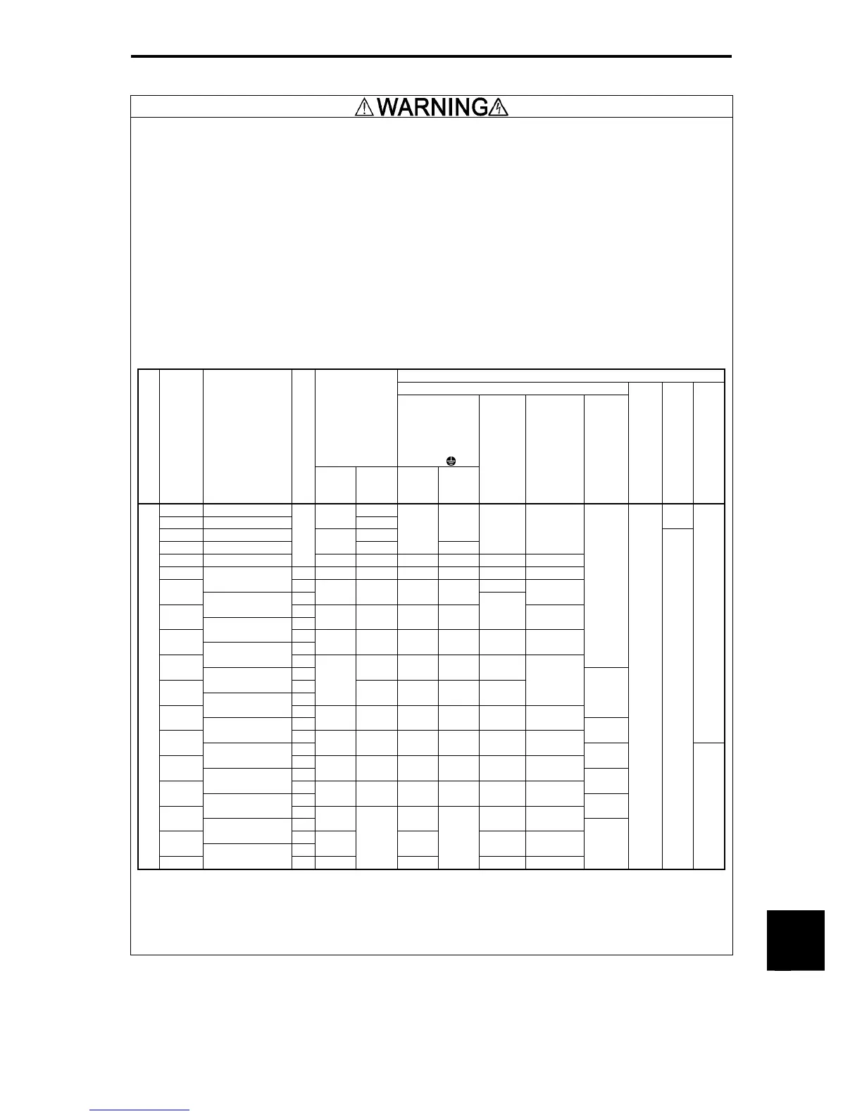
9. Use wires specified in IEC60364-5-52.
Recommended wire size (mm
2
)
Main terminal
Molded case
circuit breaker
(MCCB)
or
Earth leakage
breaker
(RCD/ELCB)
*1
Rated current
Main circuit
power inputs
[
L1/R,L2/S,
L3/T
]
*2
Grounding for
inverter[
]*3
Power supply voltage
Nominal applied motors
Inverter type
HD/LD mode
w/
DCR
w/o
DCR
w/
DCR
w/o
DCR
Inverter
outputs
[U,V,W]
*2
DC
reactor
connection
[P1,P(+)]
*2
Braking
resistor
[P(+),DB]
*2
Control circuit
terminal
Aux. control power
supply R0, T0
Aux. fan power supply
R1, T1
0.4 FRN0.4G1-2J 5
0.75 FRN0.75G1-2J
5
10
-
1.5 FRN1.5G1-2J 15
1
2.2 FRN2.2G1-2J
10
20
1
1.5
1 1
3.7 FRN3.7G1-2J
HD
20 30 2.5 4 2.5 2.5
5.5 HD 30 50 4 6 4 4
FRN5.5G1-2J
LD 6
7.5
HD
40 75 6 10 6
FRN7.5G1-2J
LD
11
HD
50 100 10 16
10
16
FRN11G1-2J
LD
15
HD
75 125 16 25 16 25
FRN15G1-2
LD
1
18.5
HD
150 25 35 25
FRN18.5G1-2
LD
22
HD
100
175 35 50 35
35
FRN22G1-2J
LD
1.5
30
HD
150 200 50 70 50 70
FRN30G1-2J
LD
2.5
-
37
HD
175 250 70 95 70 95
FRN37G1-2J
LD
4
45
HD
200 300 95 70×2 95 50×2
FRN45G1-2J
LD
6
55
HD
250 350 50×2 95×2 70×2 70×2
FRN55G1-2J
LD
10
75
HD
350 95×2 95×2 95×2
FRN75G1-2J
LD
90
HD
400 120×2 120×2 120×2
Three-phase 200 V
110
FRN90G1-2J
LD 500
-
150×2
-
150×2 150×2
-
0.75
2.5
2.5
(Note) A box (
) in the above table replaces an alphabetic letter depending on the type.
*1 The frame size and type of a MCCB or RCD/ELCB (with overcurrent protection) vary with the capacity of the power supply
transformer. Refer to the related technical documents for detailed selection.
*2 The recommended wire sizes for the main circuit terminals are examples of using a PVC wire (for 70ºC, 600 V) at a
surrounding temperature of 40ºC.
*3 Only one piece of wire with a recommended size can be connected to a ground terminal.
(To be continued)

 Loading...


