App. G Replacement Information
A-32
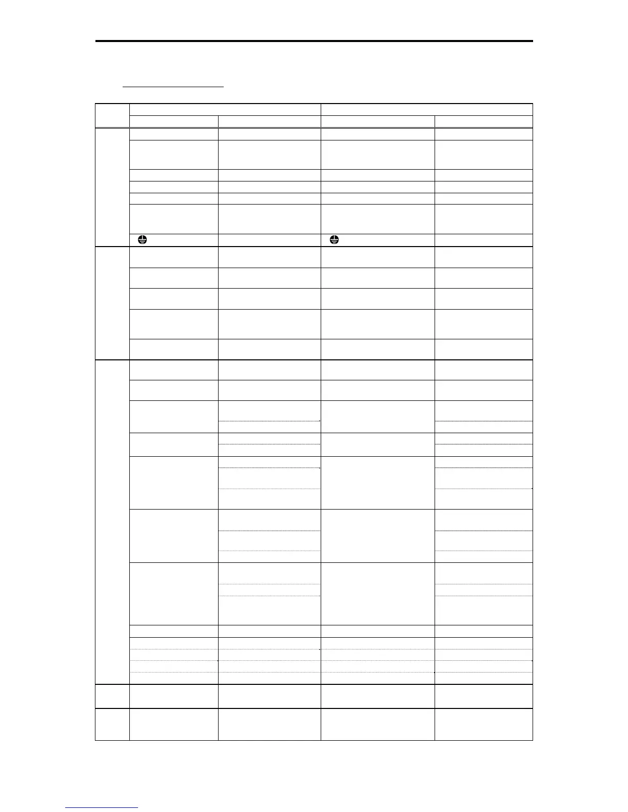
Terminal symbols and functions comparison
vs. FRENIC5000G9S/P9S
Table G-8
FRENIC5000G9S/P9S FRENIC-MEGA
Class
Terminal Signal Name Terminal Signal Name
R, S, T Main circuit power inputs L1/R, L2/S, L3/T Main circuit power inputs
R0, T0
Auxiliary power input for the
control circuit
(22 kW or below: option)
R0, T0
Auxiliary power input for
the control circuit
U, V, W Inverter outputs U, V, W Inverter outputs
P1, P(+) DC reactor connection P1, P(+) DC reactor connection
P(+), N(-) Braking unit connection P(+), N(-) DC link bus
P(+), DB
External braking resistor
connecting terminal
(Up to 7.5 kW)
P(+), DB
External braking resistor
connecting terminal
(Up to 22 kW)
Main circuit
G Grounding for inverter G Grounding for inverter
13
Power supply for the
potentiometer
13
Power supply for the
potentiometer
12
Frequency setting voltage
input
12
Frequency setting voltage
input
C1
Frequency setting current
input
C1
Frequency setting current
input
V1
Voltage input for auxiliary
setting
(22 kW or below: option)
V2
Frequency setting voltage
input
Analog input
11 Analog common
Analog input common 11 (2
terminals)
Analog common
FWD Run forward/stop command FWD
Run forward/stop
command
REV Run reverse/stop command REV
Run reverse/stop
command
X1 (Digital input 1)
Select multi-frequency (7
steps)
X1 (Digital input 1) SS1 Multi-frequency selection
UP command UP UP command
X2 (Digital input 2) Multi-frequency selection X2 (Digital input 2) SS2 Multi-frequency selection
DOWN command DOWN DOWN command
X3 (Digital input 3) Multi-frequency selection X3 (Digital input 3) SS4 Multi-frequency selection
Switch to commercial power
(50 Hz)
SW50
Switch to commercial
power (50 Hz)
Switch to commercial power
(60 Hz)
SW60
Switch to commercial
power (60 Hz)
X4 (Digital input 4) Select ACC/DEC time X4 (Digital input 4) RT1
Select ACC/DEC time(2
steps)
Select power input Hz2/Hz1
Frequency setting 2/
Frequency setting 1
Enable DC braking DCBRK Enable DC braking
X5 (Digital input 5)
Acceleration and
deceleration time selection
X5 (Digital input 5) RT2
Select ACC/DEC time(4
steps)
Select 2nd V/f M2 Select motor 2
Enable data change with
keypad
(data change allowed)
WE-KP Enable data change with
keypad
(data can be modified)
CM Digital input common CM (2 terminals) Digital input common
HLD Self hold selection X1 to X9, FWD, REV HLD Self hold selection
BX Coast-to-stop command X1 to X9, FWD, REV BX Coast-to-stop command
RST Error reset X1 to X9, FWD, REV RST Reset alarm
Digital input
THR External alarm X1 to X9, FWD, REV THR External alarm
FMA Analog monitor FMA Analog monitor
Analog
output
(11) (Analog common) (11) (Analog common)
FMP
Pulse rate monitor
(Pulse waveform output)
FMP Pulse monitor
Pulse
output
(CM) (Digital common) (CM) (Digital common)

 Loading...


