2.2 Wiring
2-23
Chapter 2 INSTALLATION AND WIRING
Table 2.2-11
Classification
Symbol Name Functional description
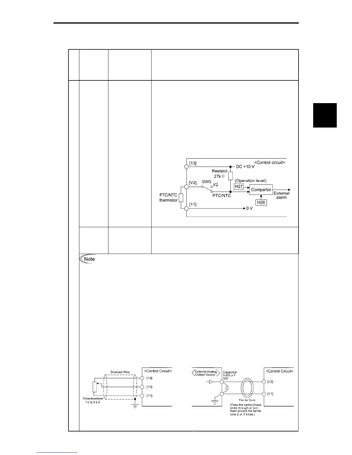
(1)
Connects PTC (Positive Temperature Coefficient)/NTC
(Negative Temperature Coefficient) thermistor for motor
protection. Ensure that the slide switch SW5 on the control
PCB is turned to the PTC/NTC position (refer to Section
2.2.7 "Setting up the slide switches").
The figure shown below illustrates the internal circuit
diagram where SW5 (switching the input of terminal [V2]
between V2 and PTC/NTC) is turned to the PTC/NTC
position. For details on SW5, refer to Section 2.2.7 "Setting
up the slide switches." In this case, you must also change
data of the function code H26.
[V2]
PTC/NTC
thermistor input
(PTC/NTC
function)
Figure 2.2-17 Internal Circuit Diagram (SW5 Selecting PTC/NTC)
[11]
Analog common
Common for analog input/output signals ([13], [12], [C1], [V2] and
[FMA]).
Isolated from terminals [CM] and [CMY].
-
Since control signal wires are handled, these signals are especially susceptible to
the external noise effects. Route the wiring as short as possible (within 20 m) and
use shielded wires. In principle, ground the shielded sheath of wires; if effects of
external inductive noises are considerable, connection to terminal [11] may be
effective.
As shown in
Figure 2.2-18, be sure to ground the single end of the shield
to enhance the shield effect.
-
Use a twin-contact relay for low level signals if the relay is used in the analog input
signal wiring. Do not connect the relay's contact to terminal [11].
-
When the inverter is connected to an external device outputting the analog signal,
the external device may malfunction due to electric noise generated by the inverter.
If this happens, according to the circumstances, connect a ferrite core (a toroidal
core or equivalent) to the device outputting the analog signal or connect a
capacitor having the good cut-off characteristics for high frequency between control
signal wires as shown in Figure 2.2-19.
-
Do not apply a voltage of +7.5 VDC or higher to terminal [C1]. Doing so could
damage the internal control circuit.
Analog input
Figure 2.2-18 Connection of Shielded Wire Figure 2.2-19 Example of Electric Noise
Reduction

 Loading...


