2.2 Wiring
2-24
Digital input terminals
Table 2.2-12
Classification
Symbol Name Functional description
[X1] Digital input 1
[X2] Digital input 2
[X3] Digital input 3
[X4] Digital input 4
[X5] Digital input 5
[X6] Digital input 6
[X7] Digital input 7
[X8] Digital input 8
[X9] Digital input 9
[FWD]
Run forward
command
Digital input
[REV]
Run reverse
command
(1)
Various signals such as "Coast to a stop," "Enable
external alarm trip," and "Select multi-frequency" can
be assigned to terminals by setting function codes E01
to E09, E98, and E99. For details, refer to Chapter 5
"FUNCTION CODES."
(2)
Input mode, i.e. SINK/SOURCE, is changeable by
using the slide switch SW1. (Refer to Section 2.2.7
"Setting up the slide switches.")
(3)
The operating mode between individual digital input
terminals and terminal CM can be switched to "ON
when shorted (active ON)" or "OFF when shorted
(active OFF)."
(4)
Digital input terminal [X7] can be defined as a pulse
train input terminal with the function codes.
Maximum wiring length: 20 m
Maximum input pulse:
30 kHz:
When connected to a pulse generator with open
collector transistor output
(Needs a pull-up or pull-down resistor. See notes
on page 2-26.)
100 kHz:
When connected to a pulse generator with
complementary transistor output
For the settings of the function codes, refer to
Chapter 5 "FUNCTION CODES."
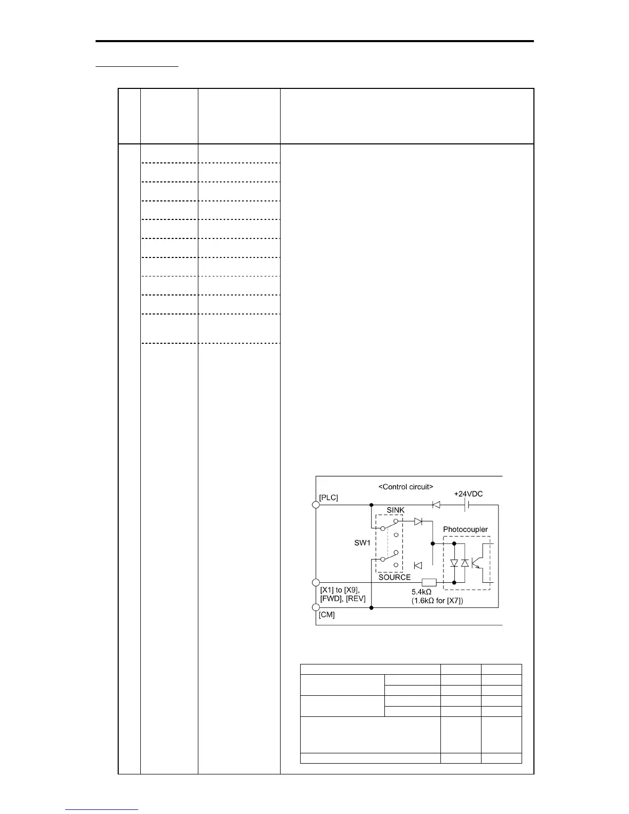
(Digital input circuit specifications)
Figure 2.2-20 Digital Input Circuit
Table 2.2-13
Item Min. Max.
ON level 0 V 2 V Operating voltage
(SINK)
OFF level 22 V 27 V
ON level 22 V 27 V Operating voltage
(SOURCE)
OFF level 0 V 2 V
Operating current at ON
(Input voltage is at 0 V)
2.5 mA 5 mA
(For [X7])
(9.7 mA)
(16 mA)
Allowable leakage current at OFF - 0.5 mA

 Loading...


