2.2 Wiring
2-25
Chapter 2 INSTALLATION AND WIRING
Table 2.2-14
Classification
Symbol Name
[PLC]
PLC signal
power
(1)
Connects to PLC output signal power supply.
Rated voltage: +24 VDC (Allowable range: +22 to +27
VDC), Maximum 100 mA DC
(2)
The terminal can also be used as a power source for the
load connected to the transistor output. Refer to
"Transistor output" described later in this table for more.
[CM] Digital common Two common terminals for digital input signals
These terminals are electrically isolated from the terminals
[11]s and [CMY].
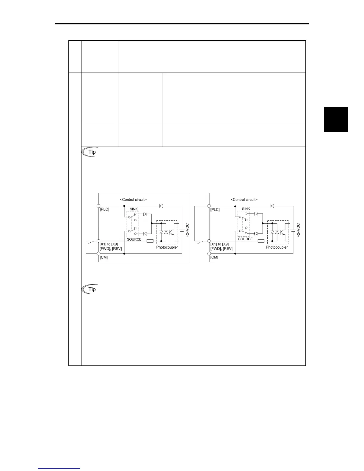
Using a relay contact to turn [X1] to [X9], [FWD], or [REV] ON or OFF
Figure 2.2-21 shows two examples of a circuit that uses a relay contact. In circuit
(a), the slide switch has been turned to SINK, whereas in circuit (b) it has been
turned to SOURCE.
Note:
To configure this kind of circuit, use a highly reliable relay.
(Recommended product: Fuji control relay Model HH54PW.)
(a) With the switch turned to SINK (b) With the switch turned to SOURCE
Figure 2.2-21 Circuit Configuration Using a Relay Contact
Digital input
Using a programmable logic controller (PLC) to turn [X1] to [X9], [FWD], or
[REV] ON or OFF
Figure 2.2-22 shows two examples of a circuit that uses a programmable logic controller
(PLC). In circuit (a), the slide switch has been turned to SINK, whereas in circuit (b) it
has been turned to SOURCE.
In circuit (a) below, short-circuiting or opening the transistor's open collector circuit in the
PLC using an external power supply turns ON or OFF control signal [X1] to [X9], [FWD],
or [REV].
When using this type of circuit, observe the following:
-
Connect the + node of the external power supply (which should be isolated from the
PLC's power) to terminal [PLC] of the inverter.
-
Do not connect terminal [CM] of the inverter to the common terminal of the PLC.

 Loading...


