2.2 Wiring
2-26
Table 2.2-15
Classification
Symbol Name Functional description
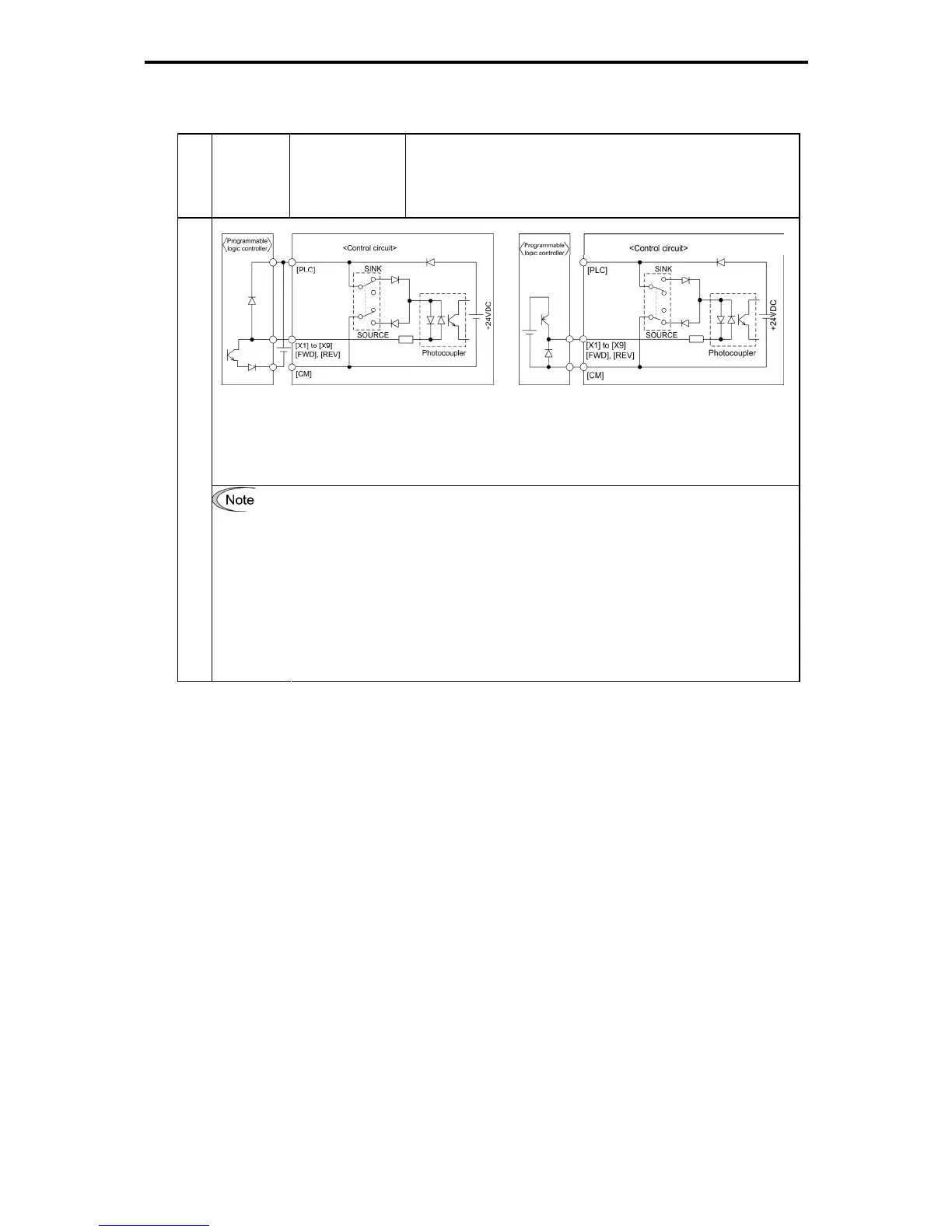
(a) With the switch turned to SINK (b) With the switch turned to SOURCE
Figure 2.2-22 Circuit Configuration Using a PLC
For details about the slide switch setting, refer to Section 2.2.7 "Setting up the slide
switches."
Digital input
For inputting a pulse train through the digital input terminal [X7]
Inputting from a pulse generator with an open collector transistor output, stray
capacity on the wiring between the pulse generator and the inverter may disable
transmission of the pulse train. As a countermeasure against this problem, insert a
pull-up resistor between the open collector output signal (terminal [X7]) and the
power source terminal (terminal [PLC]) if the switch selects the SINK mode input;
insert a pull-down resistor between the output signal (terminal [X7]) and the digital
common terminal (terminal [CM]) if the switch selects the SOURCE mode input. A
recommended pull-up/down resistor is 1 kΩ 2 W. Check if the pulse train is correctly
transmitted because stray capacity is significantly affected by the wire types and
wiring conditions.

 Loading...


