2.2 Wiring
2-30
Table 2.2-19
Classification
Symbol Name Functional description
Connecting programmable logic controller (PLC) to terminal [Y1], [Y2], [Y3]
or [Y4]
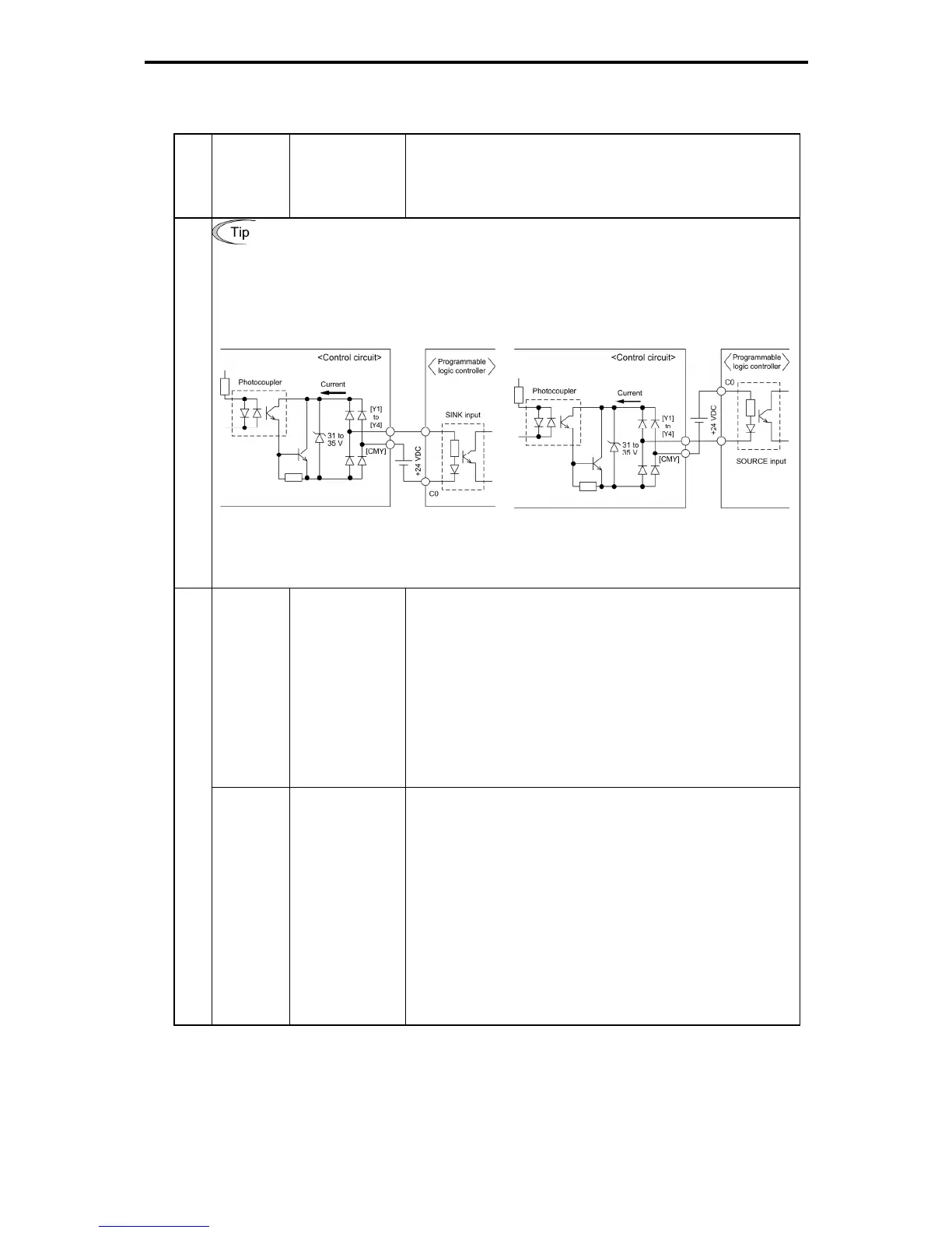
Figure 2.2-26 shows two examples of circuit connection between the transistor
output of the inverter's control circuit and a PLC. In example (a), the input circuit of
the PLC serves as a SINK for the control circuit output, whereas in example (b), it
serves as a SOURCE for the output.
(a) PLC serving as SINK
(b) PLC serving as SOURCE
Transistor output
Figure 2.2-26 Connecting PLC to Control Circuit
[Y5A/C]
General purpose
relay output
(1)
A general-purpose relay contact output usable as well as
the function of the transistor output terminal [Y1], [Y2], [Y3]
or [Y4].
Contact rating: 250 VAC 0.3 A, cos φ = 0.3,
48 VDC, 0.5 A
(2)
Switching of the normal/negative logic output is applicable
to the following two contact output modes: "Active ON"
(Terminals [Y5A] and [Y5C] are closed (excited) if the signal
is active.) and "Active OFF" (Terminals [Y5A] and [Y5C] are
opened (non-excited) if the signal is active while they are
normally closed.).
Contact output
[30A/B/C]
Alarm relay
output (for any
fault)
(1)
When the inverter stops upon an alarm, output is generated
on the relay contact (1C).
Contact rating: 250 VAC 0.3 A, cos φ = 0.3,
48 VDC, 0.5 A
(2)
Any one of output signals assigned to terminals [Y1] to [Y4]
can also be assigned to this relay contact to use it for signal
output.
(3)
Switching of the normal/negative logic output is applicable
to the following two contact output modes: "Active ON"
(Terminals [30A] and [30C] are closed (excited) if the signal
is active.) and "Active OFF" (Terminals [30A] and [30C] are
opened (non-excited) if the signal is active while they are
normally closed.).

 Loading...


