2.2 Wiring
2-29
Chapter 2 INSTALLATION AND WIRING
Table 2.2-17
Classification
Symbol Name Functional description
[Y1]
Transistor
output 1
[Y2]
Transistor
output 2
[Y3]
Transistor
output 3
[Y4]
Transistor
output 4
(1)
Various signals such as Inverter Running, Frequency Arrival
and Overload Early Warning can be output from these
terminals by setting function code E20 to E24. Refer to
Chapter 5 "FUNCTION CODES" for details.
(2)
The operating mode between transistor output terminals [Y1]
to [Y4] and terminal [CMY] can be switched to "ON at signal
output (active ON)" or "OFF at signal output (active OFF)."
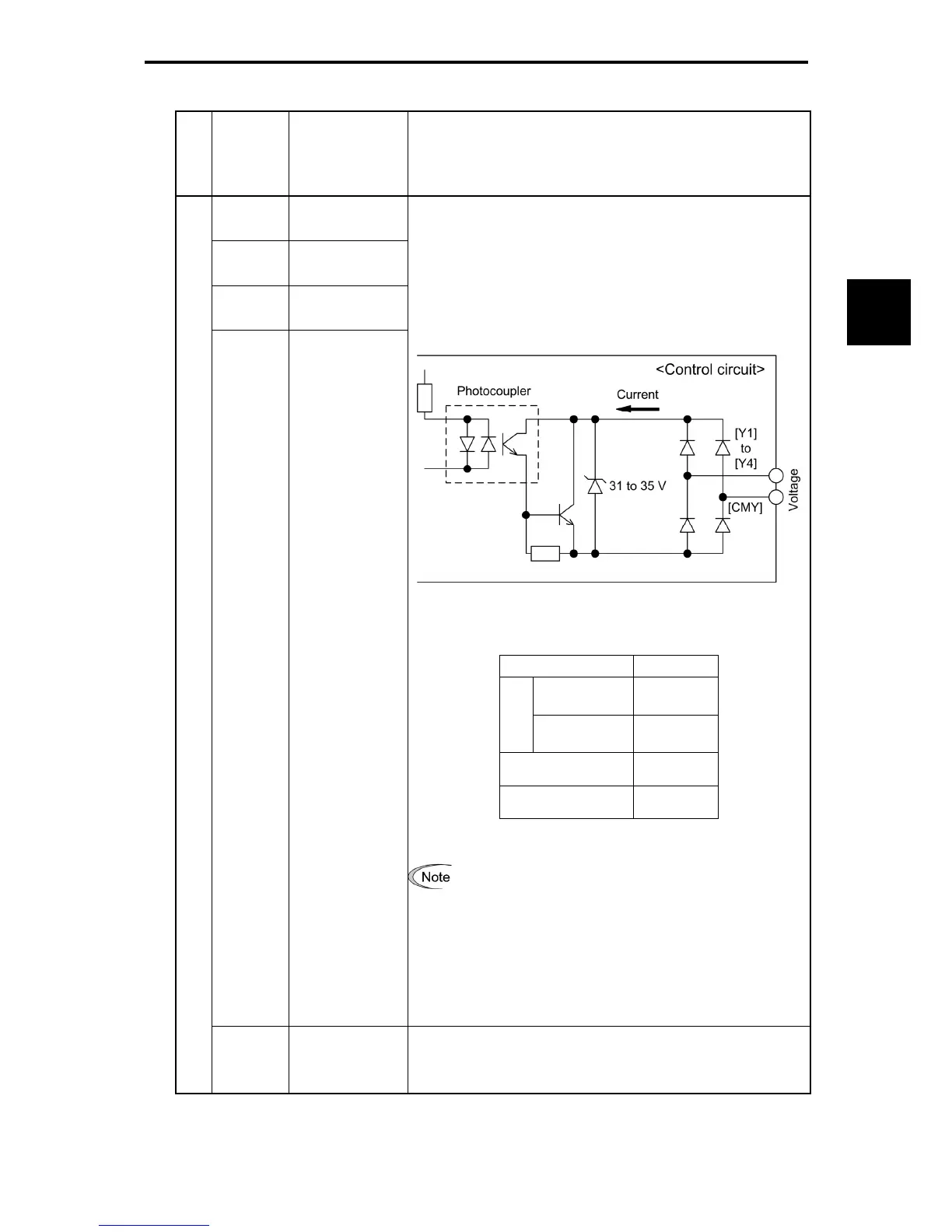
(Transistor output circuit specifications)
Figure 2.2-25 Transistor Output Circuit
Table 2.2-18
Item Max.
ON level 2V
Operating
voltage
OFF level 27V
Maximum motor
current at ON
50 mA
Leakage current at
OFF
0.1 mA
Figure 2.2-26 shows examples of connection between the control
circuit and a PLC.
•
When a transistor output drives a control relay,
connect a surge-absorbing diode across relay's coil
terminals.
•
When any equipment or device connected to the
transistor output needs to be supplied with DC power,
feed the power (+24 VDC: allowable range: +22 to
+27 VDC, 100 mA max.) through the [PLC] terminal.
Short-circuit between the terminals [CMY] and [CM] in
this case.
Transistor output
[CMY]
Transistor output
common
Common terminal
for transistor output signals.
This terminal is electrically isolated from terminals [CM]s and
[11]s.

 Loading...


