RC n,m The RC command begins data collection. Sets data capture time interval where n
is an integer between 1 and 8 and designates 2
n
msec between data. m is optional
and specifies the number of elements to be captured. If m is not defined, the
number of elements defaults to the smallest array defined by DM. When m is a
negative number, the recording is done continuously in a circular manner. _RD is
the recording pointer and indicates the address of the next array element. n=0
stops recording.
RC? Returns a 0 or 1 where, 0 denotes not recording, 1 specifies recording in progress
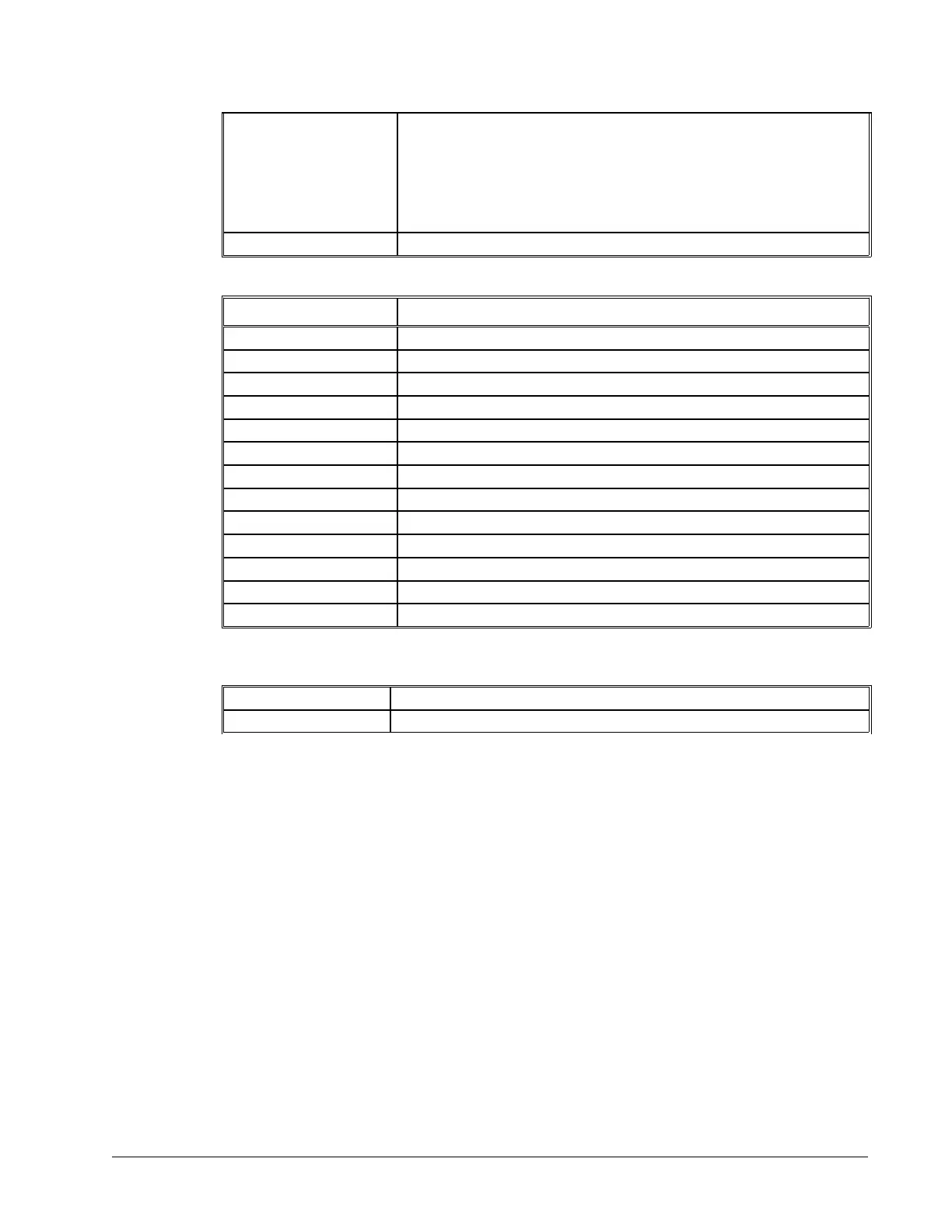
Data Types for Recording:
Data type Description
TIME Controller time as reported by the TIME command
_AFn Analog input (n=X,Y,Z,W,E,F,G,H, for AN inputs 1-8)
_DEX 2
nd
encoder position (dual encoder)
_NOX Status bits
_OP Output
_RLX Latched position
_RPX Commanded position
_SCX Stop code
_TEX Position error
_TI Inputs
_TPX Encoder position
_TSX Switches (only bit 0-4 valid)
_TTX Torque (reports digital value +/-32544)
Note: X may be replaced by Y,Z or W for capturing data on other axes.
Operand Summary - Automatic Data Capture
_RC Returns a 0 or 1 where, 0 denotes not recording, 1 specifies recording in progress
_RD Returns address of next array element.
Example - Recording into An Array
During a position move, store the X and Y positions and position error every 2 msec.
#RECORD Begin program
DM XPOS[300],YPOS[300] Define X,Y position arrays
DM XERR[300],YERR[300] Define X,Y error arrays
RA XPOS[],XERR[],YPOS[],YERR[] Select arrays for capture
RD _TPX,_TEX,_TPY,_TEY Select data types
PR 10000,20000 Specify move distance
RC1 Start recording now, at rate of 2 msec
BG XY Begin motion
#A;JP #A,_RC=1 Loop until done
MG “DONE” Print message
EN End program
#PLAY Play back
N=0 Initial Counter
JP# DONE,N>300 Exit if done
N= Print Counter
DMC-40x0 User Manual Chapter 7 Application Programming • 156