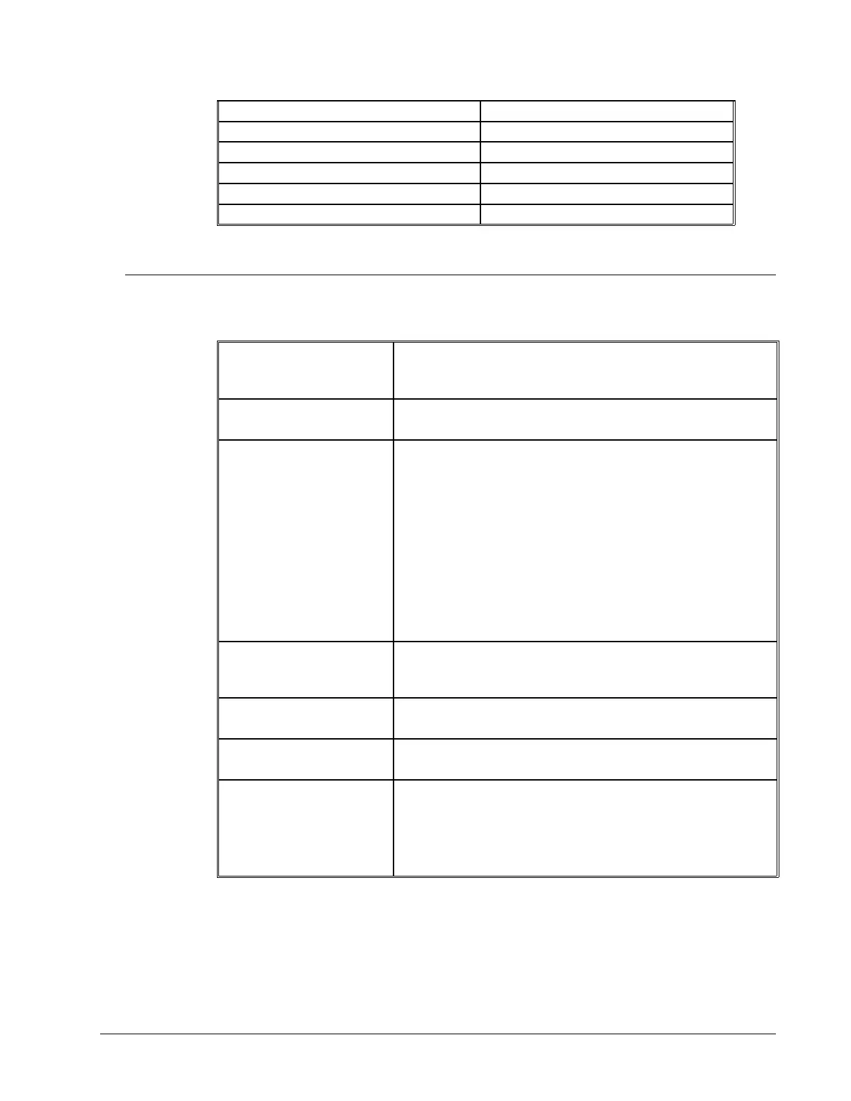
4 RTS 8 CTS
3 TXD 2 RXD
2 RXD 3 TXD
1 CTS 7 RTS
5 GND 5 GND
Controller +5V 9 (Jumper APWR if required)
Pin-Out Description for DMC-40x0
Outputs
Motor Command +/- 10 Volt range signal for driving amplifier. In servo mode,
motor command output is updated at the controller sample rate. In
the motor off mode, this output is held at the OF command level.
Amplifier Enable Signal to disable and enable an amplifier. Amp Enable goes low on
Abort and OE1.
PWM / Step PWM/STEP OUT is used for directly driving power bridges for DC
servo motors or for driving step motor amplifiers. For servo
motors: If you are using a conventional amplifier that accepts a +/-
10 Volt analog signal, this pin is not used and should be left open.
The PWM output is available in two formats: Inverter and Sign
Magnitude. In the Inverter mode, the PWM (64kHz) signal is .2%
duty cycle for full negative voltage, 50% for 0 Voltage and 99.8%
for full positive voltage (64kHz Switching Frequency). In the Sign
Magnitude Mode (MT1.5), the PWM (128 kHz) signal is 0% for 0
Voltage, 99.6% for full voltage and the sign of the Motor
Command is available at the sign output (128kHz Switching
Frequency).
PWM / Step For stepper motors: The STEP OUT pin produces a series of pulses
for input to a step motor driver. The pulses may either be low or
high. The pulse width is 50%.
Sign / Direction Used with PWM signal to give the sign of the motor command for
servo amplifiers or direction for step motors.
Error The signal goes low when the position error on any axis exceeds
the value specified by the error limit command, ER.
Output 1-Output 8
Output 9-Output 16
(DMC-4050 thru 4080)
The high power optically isolated outputs are uncommitted and
may be designated by the user to toggle relays and trigger external
events. The output lines are toggled by Set Bit, SB, and Clear Bit,
CB, instructions. The OP instruction is used to define the state of
all the bits of the Output port.
DMC-40x0 User Manual Appendices • 208