Figure 3-2. Connecting a single Limit or Home Switch to an Isolated Supply. This diagram only shows the connection for the
forward limit switch of the X axis.
Bypassing the Opto-Isolation:
If no isolation is needed, the internal 5 Volt supply may be used to power the switches. This can be done by
connecting LSCOM or INCOM to 5V.
To close the circuit, wire the desired input to any ground (GND) pin on the controller.
TTL Inputs
The Auxiliary Encoder Inputs
The auxiliary encoder inputs can be used for general use. For each axis, the controller has one auxiliary encoder and
each auxiliary encoder consists of two inputs, channel A and channel B. The auxiliary encoder inputs are mapped to
the inputs 81-96.
Each input from the auxiliary encoder is a differential line receiver and can accept voltage levels between +/- 12
volts. The inputs have been configured to accept TTL level signals. To connect TTL signals, simply connect the
signal to the + input and leave the - input disconnected. For other signal levels, the - input should be connected to a
voltage that is ½ of the full voltage range (for example, connect the - input to 6 volts if the signal is a 0 - 12 volt
logic).
Example:
A DMC-4010 has one auxiliary encoder. This encoder has two inputs (channel A and channel B). Channel A input
is mapped to input 81 and Channel B input is mapped to input 82. To use this input for 2 TTL signals, the first
signal will be connected to AA+ and the second to AB+. AA- and AB- will be left unconnected. To access this
input, use the function @IN[81] and @IN[82].
NOTE: The auxiliary encoder inputs are not available for any axis that is configured for stepper motor.
Chapter 3 Connecting Hardware • 37 DMC-40x0 User Manual
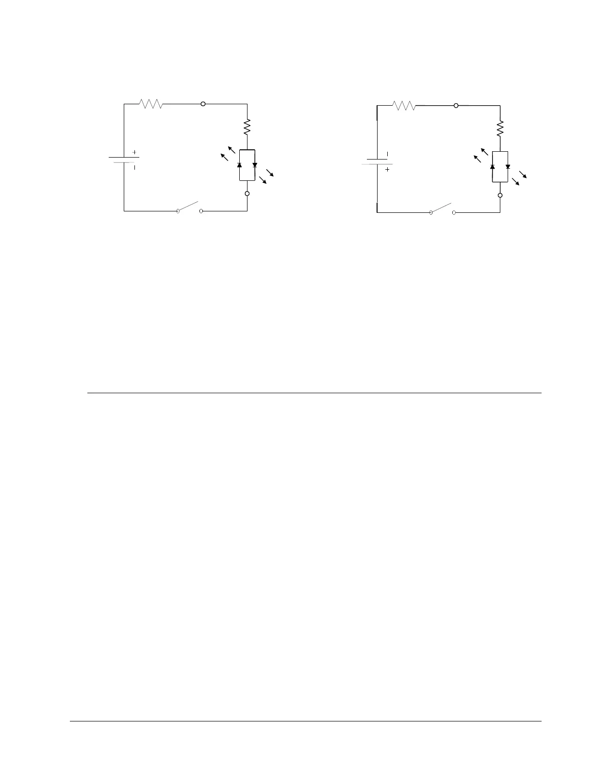
LSCOM
FLSX
External Resistor Needed for
Voltages > 28V
LSCOM
FLSX
External Resistor Needed for
Voltages > 28V
Configuration to source current at the
LSCOM terminal and sink current at
switch inputs
Configuration to sink current at the
LSCOM terminal and source current at
switch inputs
2.2K
2.2K