Theory of Operation
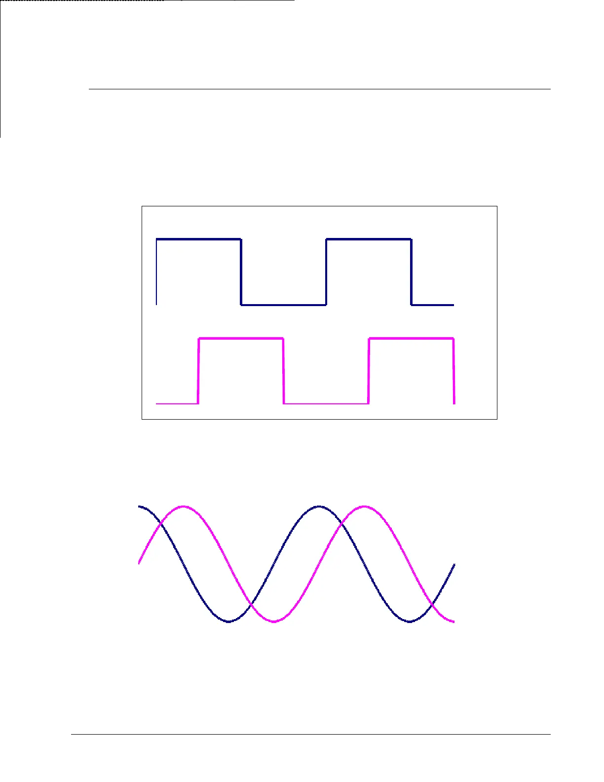
Traditional quadrature rotary encoders work by having two sets of lines inscribed radially around the circumference
of an optical disk. A light is passed through each of these two sets of lines. On the other side of the gratings, photo
sensors detect the presence (or absence) of these lines. These two sets of lines are offset from each other such that
one leads the other by one quarter of a complete cycle as shown in Figure 3 below. These signals are commonly
referred to as the Channels A and B. The direction of rotation of the encoder can be inferred by which of the A and
B signals leads the other. Each rising or falling edge indicates one quadrature count. Thus for a complete cycle of
the square wave there are a total of four encoder counts.
Figure A7-22: Quadrature Encoder Signals
A sinusoidal encoder is similar to a quadrature encoder in that it produces two signals that are read from two sets of
lines inscribed on an optical disk. The difference is that the two signals are output as analog sinusoidal waves as
shown in Figure A7-22: Quadrature Encoder Signals.
Figure A7-23: Sinusoidal Encoder Signals
When the DMC-40x0 is ordered with the ICM-42100, the position is tracked on two levels. First, the number of
coarse cycles is counted much like is done with a quadrature encoder. On the fine level the precise position inside
the cycle is determined from the two sinusoidal signals using bit-wise interpolation. This interpolation can be set by
DMC-40x0 User Manual A7 – ICM-42100 (-I100) • 266
Channel A
Channel B
V
a
V
b


 To Next Page