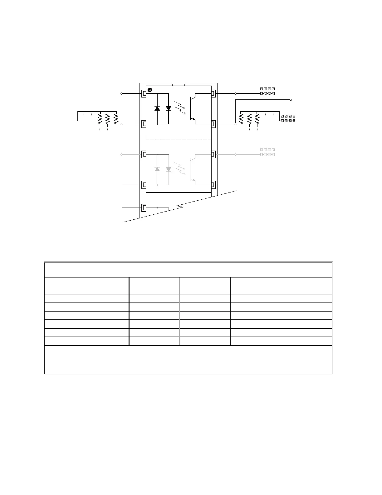
Amplifier Enable Circuit
Sourcing Output Configuration
(Pin 1 of LTV8441 in Pin 1 of Socket U4)
TTL level Amp
Enable signal
from controller
(SH = 5V, MO = 0V)
TTL level Amp
Enable signal
from controller
(SH = 5V, MO = 0V)
5V or GND
PIN 1
RP2 (470 Ohm)
Pin 1
of socket
Pin 1
LTV8441
Socket U4
RP6 (820 Ohm)
+5 V
GND
AEC2
+12 V
+5 V
GND
AEC2
+12 V
Amp Enable Output to Drive
(AENn)
AECOM1
AECOM2
JP2
AECOM2
+12 V
AEC1
+5 V
GND
JP2
JP1
Figure 3-5: Amplifier Enable Circuit Sourcing Output Configuration
Sourcing Configuration (pin1 of LTV8441 chip in pin1 of socket U4)
Logic State JP1 JP2
RP2
(square pin next to RP2 label is 5V)
5V, HAEN GND – AECOM1 5V – AECOM2 Dot on R-pack opposite RP2 label
5V, LAEN GND – AECOM1 5V – AECOM2 Dot on R-pack next to RP2 label
12V, HAEN GND – AECOM1 +12V – AECOM2 Dot on R-pack opposite RP2 label
12V, LAEN GND – AECOM1 +12V – AECOM2 Dot on R-pack next to RP2 label
Isolated 24V, HAEN AEC1 – AECOM1 AEC2 - AECOM2 Dot on R-pack opposite RP2 label
Isolated 24V, LAEN AEC1 - AECOM1 AEC2 – AECOM2 Dot on R-pack next to RP2 label
For 24V isolated enable, tie +24V of external power supply to AEC2 at the D-sub, tie common return to AEC1. Replace
RP6 with a 4.7 kΩ resistor pack. For Axes A-D, AEC1 and AEC2 are located on the EXTERNAL DRIVER (A-D) D-Sub
connector. For Axes E-H, AEC1 and AEC2 are located on the EXTERNAL DRIVER (E-H) D-Sub connector. Note:
AEC1 and AEC2 for axes A-D are NOT connected to AEC1 and AEC2 for axes E-H.
Table3-3: Sourcing Configuration
Chapter 3 Connecting Hardware • 43 DMC-40x0 User Manual