AT600 User’s Manual 9
Chapter 2. Installation
2.4.2a Dual Traverse Installation at Transducer Spacing Range 0 to 250mm (cont.)
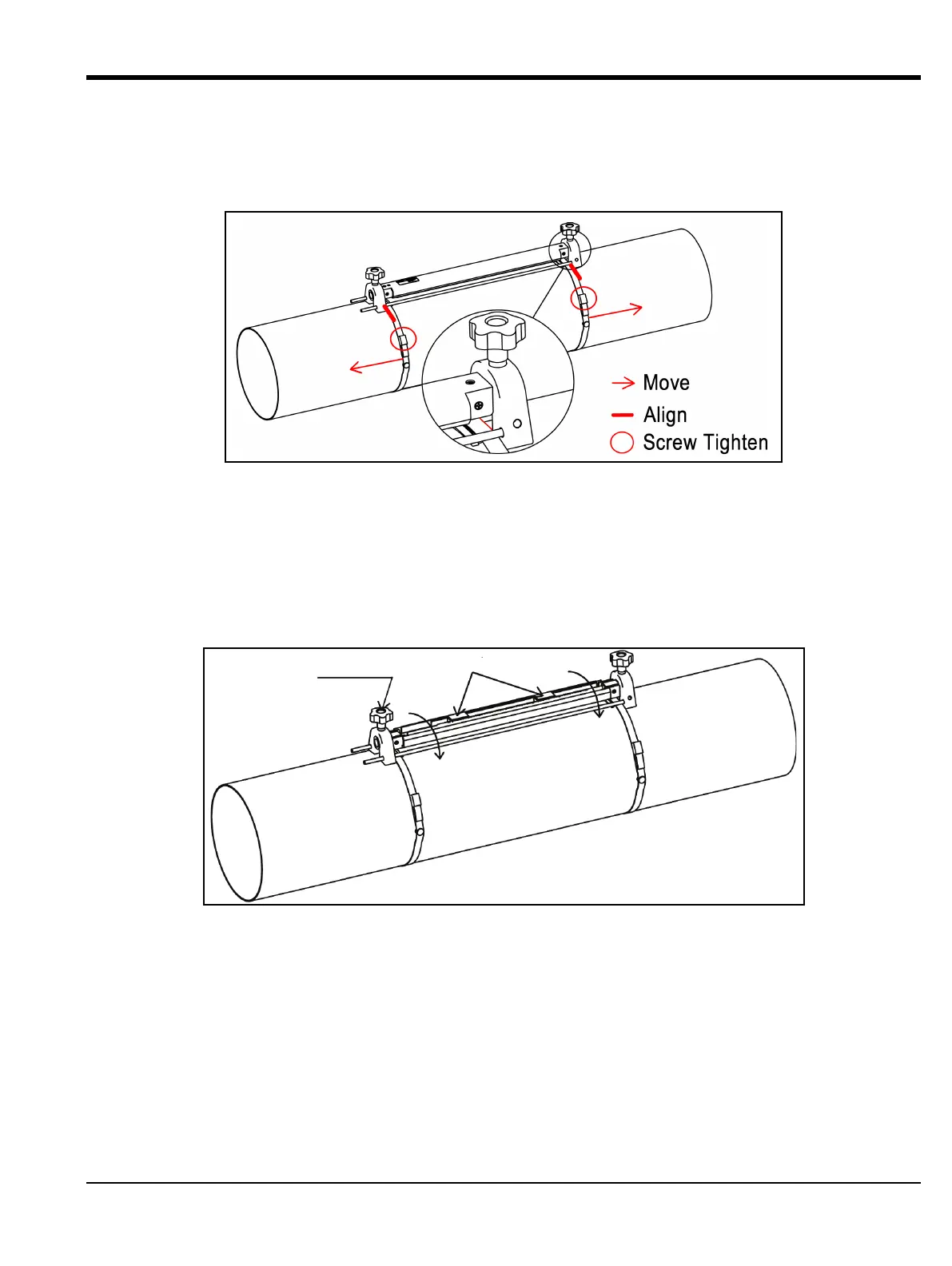
c. Put clamp-on fixture on pipe and move straps onto sides of fixture, then tighten screw on straps and validate
strapping stays within sides of fixture.
Figure 10: Clamp-on Fixture Installation
2. Wire power and transducer cables to the AT600; refer to Figure 22 on page 16.
3. Power meter and program flow meter to determine transducer spacing.(See AT600 Programming in Chapter 3.)
4. Set spacing between the two transducers and tighten back onto the pipe.
a. Loosen hand rails and rotate fixture so the transducers are in view.
Figure 11: Transducer View
b. Set spacing between transducers, remove laminar piece on couplant, apply couplant to transducer and rotate
back onto rail.
 Loading...


