AT600 User’s Manual 21
Chapter 2. Installation
2.6.5 Wiring Modbus Communication
The AT600 is equipped with an optional Modbus communication port. The port is a two-wire, half-duplex RS485
interface. The standard AT600 disables the Modbus communication. Proceed to the appropriate configuration for menu
instructions to activate the Modbus communication.
To wiring Modbus RS485 serial port, refer to Figure 22 on page 16 and complete the following steps:
1. Disconnect the main power to the unit.
2. Install the required cable clamp in the chosen gland hole on the side of the electronics enclosure.
3. Feed one end of the cable through the gland hole, wire it to terminal block and secure the cable gland as shown
in Figure 22 on page 16.
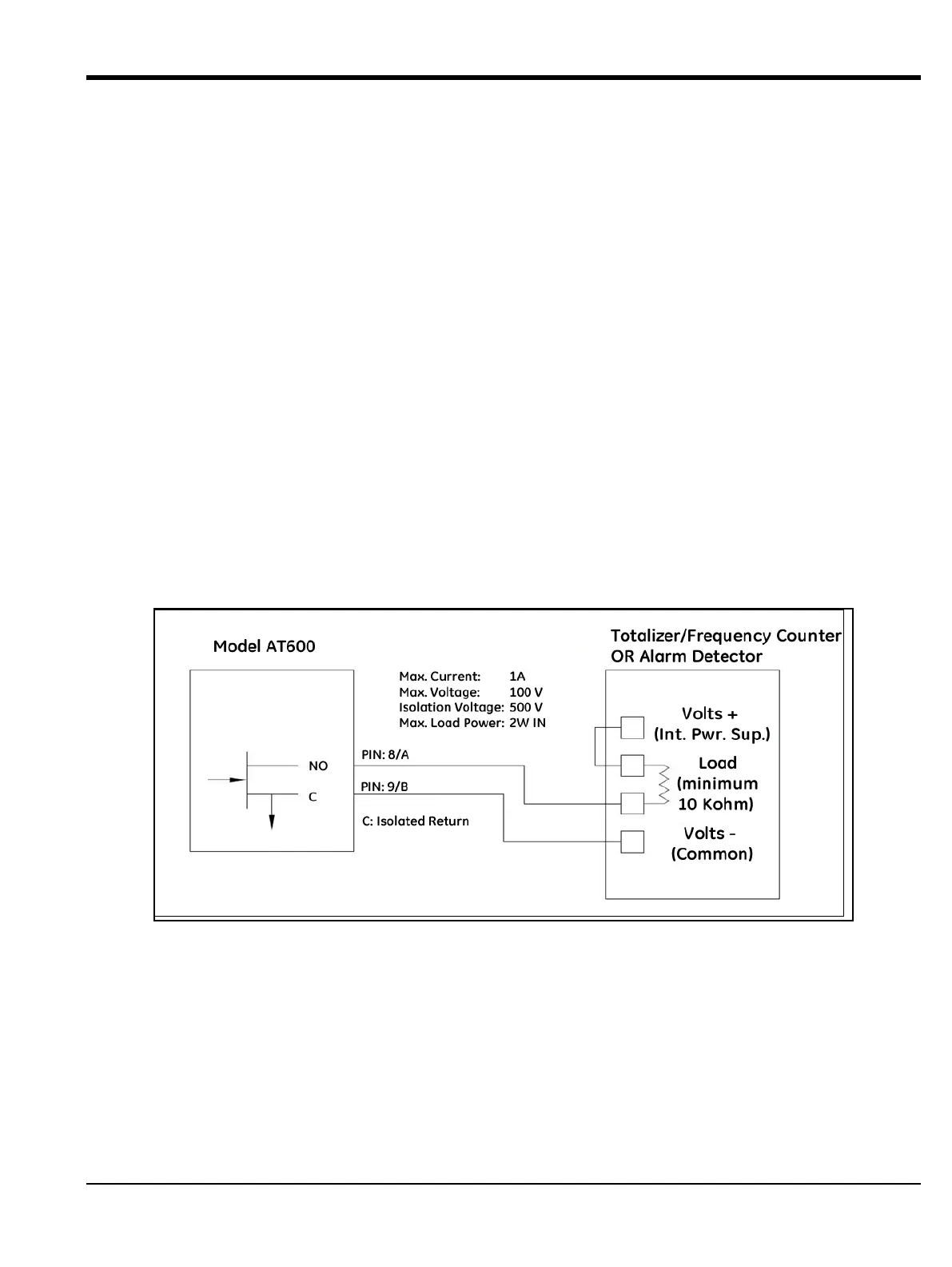
2.6.6 Wiring Frequency/Totalizer/Alarm Output
The AT600 can accommodate up to 2 channels of totalizer/frequency/alarm outputs. Each totalizer/frequency/alarm
can be configured as totalizer, frequency or alarm output by software setting. Refer to 3.6.4 section for the output
setting.
Each totalizer/frequency/alarm output requires two wires. Wire this terminal block in accordance with the pin number
assignments shown in Figure 27 below. Figure 22 shows sample wiring diagrams of totalizer/frequency/alarm output
circuit.
Figure 27: Totalizer/Frequency/Alarm Output Wiring