Chapter 2. Installation
16 AT600 User’s Manual
2.6 Making Electrical Connections
ATTENTION EUROPEAN CUSTOMERS!! To meet CE Mark requirements, all cables must be installed as
described in Appendix D, CE Mark Compliance.
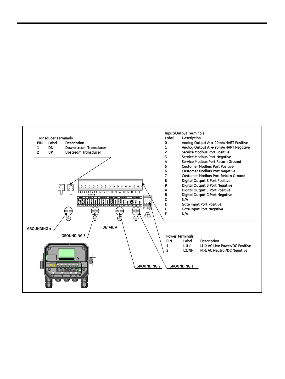
This section contains instruction for making all the necessary electrical connections to the AT600 flowmeter. Refer to
Figure 22 below for the complete wiring diagram of the unit.
IMPORTANT: Except for the transducer connector, all electrical connectors are stored in their terminal blocks during
shipment and may be removed from the enclosure for more convenient wiring. Feed the cables through
the cable gland holes on the bottom of the enclosure, attach the wires to the appropriate connectors and
plug the connectors back into their terminal blocks.
Once the AT600 is completely wired, proceed to Chapter 3, Initial Setup, to configure the unit for operation.
Figure 22: Wiring Diagram
Note: HART or MODBUS communication are optional selections for the AT600 electronics and must be chosen at
the time of ordering.
To lead the wiring cables into the enclosure, power lines, transducer line and I/O lines are distributed to different gland
holes. Refer to Appendix A, section A.2 for cable criteria. Be sure to select the cable to connect the meter only to the
specified cables.