AT600 User’s Manual 19
Chapter 2. Installation
2.6.2 Wiring the Transducers
ATTENTION EUROPEAN CUSTOMERS! To meet CE Mark requirements, all cables must be installed as described
in Appendix C, CE Mark Compliance.
Wiring a typical AT600 ultrasonic liquid flow meter system requires interconnection of the following components:
• A pair of transducers installed inside the fixture;
• The electronics console
To wire the transducers, complete the following steps:
1. Locate the transducer cables and connect them to the two transducers.
2. Connect the cable connector with yellow "DN" jacket on the cable to DN and connect cable connector with
white "UP" jacket on the cable to UP as shown in Figure 22 on page 16. Then, secure the cable gland.
3. Make vertical insertion when the cable connector is plugged into the receptacle to avoid destroying the
connector.
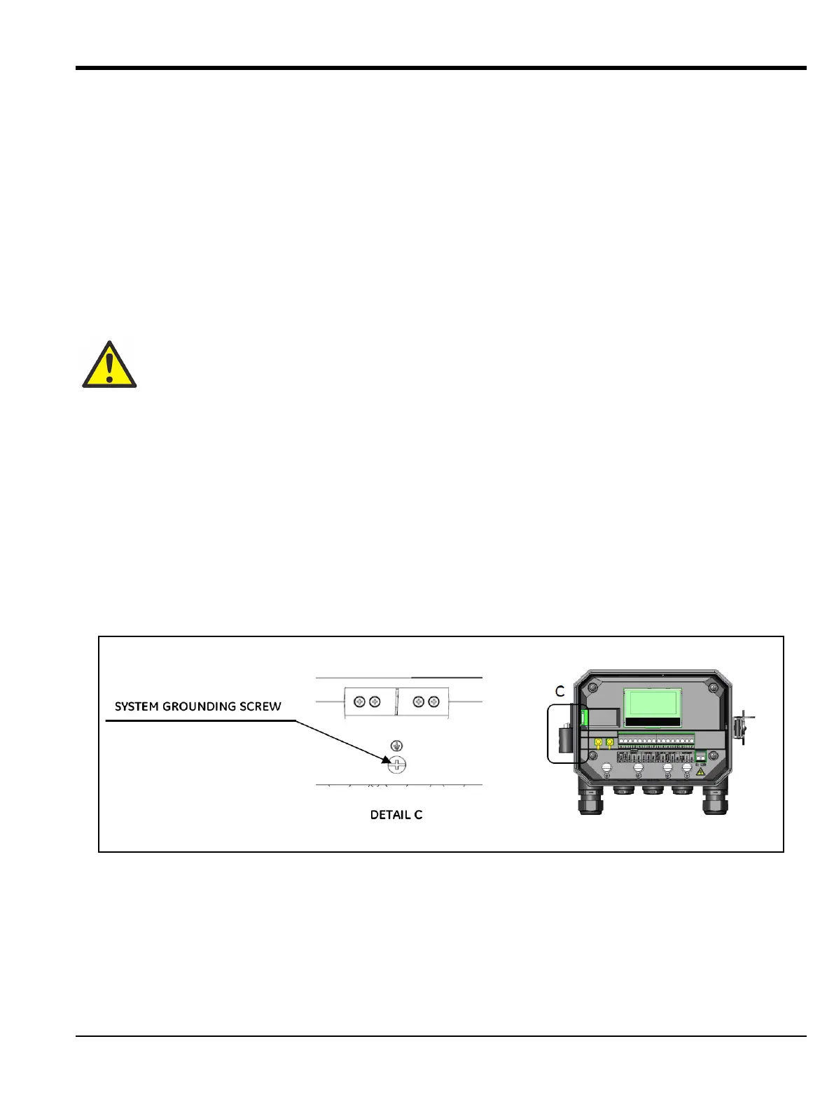
2.6.3 Wiring System Ground
Proper system ground must be connected to an AT600 Meter. Refer to Figure 25 to locate the system ground screw.
This ground screw must be connected to a safe ground in the field.
Figure 25: System Grounding Screw
WARNING! Before connecting the transducers, take them to a safe area and discharge any static
build-up by shorting the center conductor of the transducer cables to the metal shield on the cable
connector.