Chapter 2. Installation
18 AT600 User’s Manual
2.6.1 Wiring the Line Power (cont.)
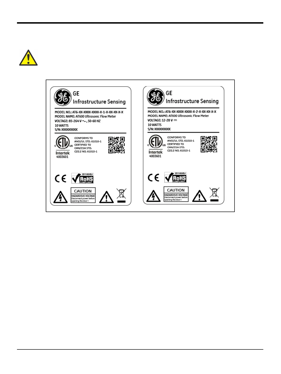
Figure 24: Meter SN Label Example (AC and DC Version):
1. Strip 1/4" of insulation from the end of the power and neutral or line leads (or the positive and negative DC
power leads), and 1/2" from the end of the ground lead.
2. Connect the ground lead to the internal ground connection (GROUNDING 1) located on the bottom panel of
the enclosure (See Figure 22).
IMPORTANT: The incoming ground lead must be connected to the internal ground connection.
3. Connect the neutral or line lead (or the negative - DC power lead) to L2/N(-) and the line power lead (or the
positive +DC power lead) to L1(+) as shown in Figure 22 on page 16.
IMPORTANT: Do not remove the existing PC board ground wire or the cover ground wire.
WARNING! Improper connection of the line power leads or connecting the meter to the incorrect
line voltage will damage the unit. It will also result in hazardous voltages at the flowcell and
associated piping and within the electronics console.