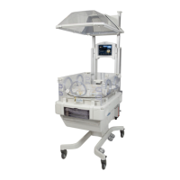
LOF-4 Service Manual
FIGURE 8-17. Base and Elevating Column............................................................................................ 8-34
FIGURE 8-18. Right (East) Upright Parts, Motor Side (Complete East Rail Assembly:
6600-0290-850) Motor Not included ................................................................................................... 8-36
FIGURE 8-19. Belt Channel - 1 (Lift Motor Side).................................................................................. 8-38
FIGURE 8-20. Lift Rail (Both Sides)............................................................................................................. 8-40
FIGURE 8-21. Rail End Caps......................................................................................................................... 8-42
FIGURE 8-22. Left (West) Upright (Complete West Rail Assembly: 6600-0290-851)......... 8-44
FIGURE 8-23. Compartment Sensor........................................................................................................ 8-45
FIGURE 8-24. Servo Control Oxygen Sensor Housing Assembly (Servo O2 Upgrade Kit
6600-0678-800)............................................................................................................................................. 8-47
FIGURE 8-25. Servo Control Oxygen Valve Housing ........................................................................ 8-49
FIGURE 8-26. Expansion Chamber/Heatsink Vent............................................................................ 8-50
FIGURE 8-27. Servo Control Oxygen Cooling Fan ............................................................................. 8-51
FIGURE 8-28. Servo Control Oxygen PC Board................................................................................... 8-52
FIGURE 8-29. Manifold Endcap Safety Valve.......................................................................................8-53
FIGURE 8-30. Storage Drawer.................................................................................................................... 8-54
FIGURE 8-31. Instrument Shelf CN (M1082912)................................................................................. 8-55
FIGURE 8-32. Monitor Shelf CN (M1082910)........................................................................................8-56
FIGURE 8-33. Cylinder Holders................................................................................................................... 8-57
FIGURE 8-34. Tubing Management Arm (6600-0837-800)........................................................... 8-58
FIGURE 8-35. Dovetail Mount DIN Rail (6600-0659-803)............................................................... 8-59
FIGURE 8-36. Silo Support Assembly (6600-0853-800).................................................................. 8-60
FIGURE 8-37. Rotating I.V. Pole Assembly (6600-0851-800)......................................................... 8-61
FIGURE 8-38. Dovetail Extension (6600-0852-800).......................................................................... 8-62
FIGURE 8-39. Control Board (2080962-001) ........................................................................................8-72
FIGURE 8-40. SBC (2074306-001) ............................................................................................................. 8-73
FIGURE 8-41. Relay Board (Service Kit: 2080429-001).................................................................... 8-74
FIGURE 8-42. Wiring Diagram: Control Board..................................................................................... 8-75
FIGURE 8-43. Wiring Diagram: Elevating Base, Hood, and Motors........................................... 8-76
FIGURE 8-44. Wiring Diagram: Electrical Enclosure......................................................................... 8-77
FIGURE 8-45. Wiring Diagram: Control Panel......................................................................................8-78
FIGURE 8-46. Wiring Diagram: Incubator and Warmer Heater ................................................. 8-79
FIGURE 8-47. Wiring Diagram: Servo Humidifier .............................................................................. 8-80
FIGURE 8-48. Wiring Diagram: Servo Control Oxygen.................................................................... 8-81

 Loading...