Section 1 — Introduction
17
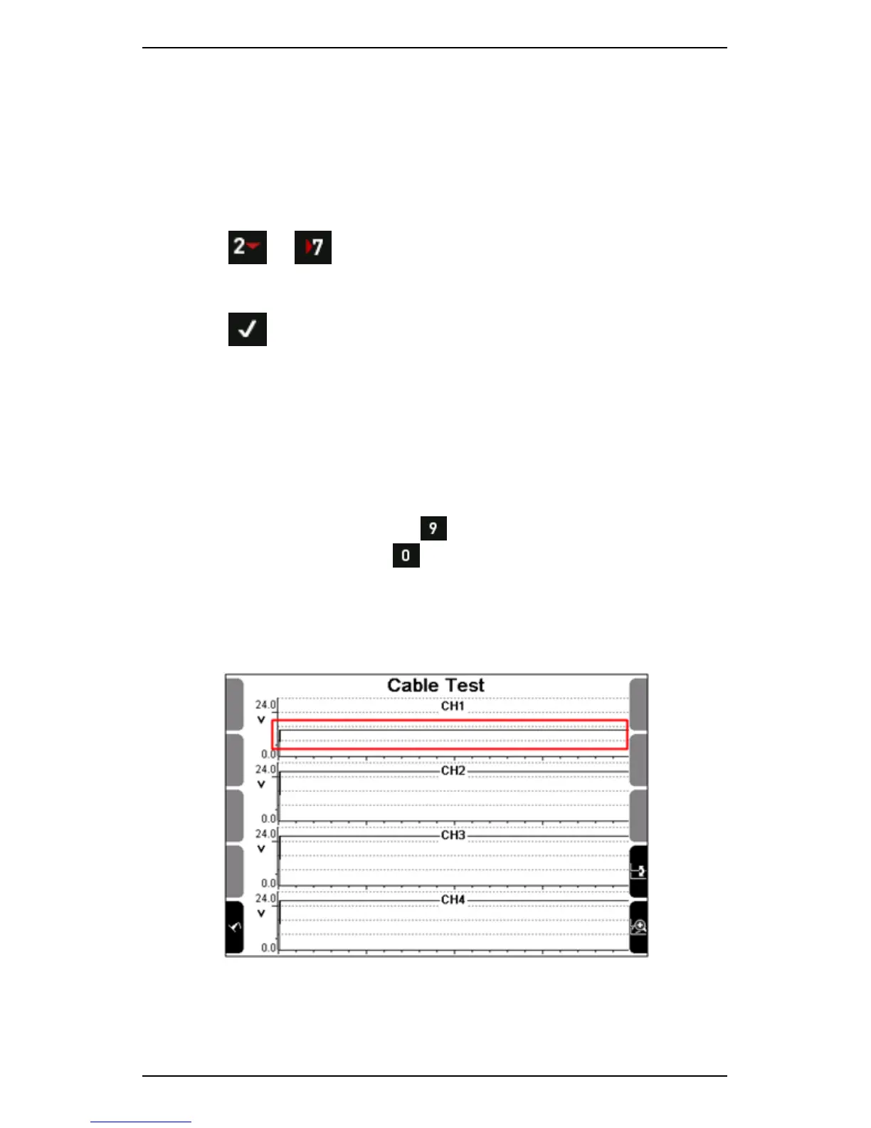
Cable Test
To display a live bias voltage graph of all connected channels and
determine whether your sensors and cables are working correctly:
1. Secure your sensor so that it does not move — You could attach it to
a machine that is not running or hold it with a clamp.
2. Press or Measure.
3. Use the navigation keys provided to scroll down and select Cable
Test.
4. Press — The current voltage displays in real time.
5. Move the cable joints to determine whether there is an intermittent
short:
• Consistent data (e.g. a straight line) indicates the cable is
working correctly.
• Varying data (e.g. a varying line) indicates there is a problem
with the cable.
TIP: You can view the data that displays for a particular channel in
more detail. To do this, press to toggle and select the channel
you wish to view > Press to access an enlarged view of the
data.
NOTE: You can run a cable test for any standard sensor that is
supported by your instrument, including accelerometers, velocity
sensors, and proximity probes.
Cable test reveals sensor is functioning correctly
 Loading...


