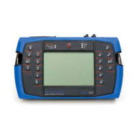
Do you have a question about the GE SCOUT140-Ex and is the answer not in the manual?
Warnings and recommendations for safe instrument operation.
Information on instrument ratings for hazardous environments.
Overview of analyzing and correcting rotor mass imbalance.
Instructions for proper accelerometer setup and attachment.
Instructions for connecting and setting up the tachometer.
Method for diagnosing faults using phase analysis.
Procedure for performing modal impact tests.
Choosing preferred measurement units and spectrum scaling.
Setting default parameters for measurement types.
Creating and reusing custom measurement parameter sets.
Specifying sensor assignments for instrument channels.
Step-by-step guide to taking recordings on the instrument.
Using baseline recordings to assess data quality of new measurements.
Quick guide to measuring and analyzing machine vibration onsite.
Adjusting the amplitude scale (Linear, Log, dB) for spectrum displays.
Steps to transfer recorded data from instrument to Ascent software.
Steps to transfer data folders from Ascent software to the instrument.
Transferring data to/from instrument using a USB flash drive.
Step-by-step guide to collecting recordings following a route.
Comparing measurements against baseline and alarms during route collection.
Recording data from multiple channels simultaneously on a route.
Configuring triaxial recordings using a triax sensor.
Defining measurement settings and parameters for reuse.
Defining, editing, and managing sensors for measurements.
Emptying the instrument database to restore factory settings.
Overview of balancing rigid rotors and the balancing process.
Configuring job settings for rotor balancing operations.
Setting balance job type and weight placement reference system.
Initial setup for creating a new rotor balancing job.
Measuring the initial imbalance of the rotor.
Attaching and measuring with a trial weight to assess imbalance correction.
Attaching correction weights based on instrument recommendations.
Fine-tuning the balance by taking trim readings.
Reviewing and saving the results of a balancing job.
Reviewing optional features and upgrading instrument firmware.
Procedure to reset an unresponsive instrument.
| Resolution | 0.1 dB |
|---|---|
| Operating Temperature | -20°C to +50°C |
| Battery Life | >30 hours |
| Display | LCD |
| Weight | Approx. 300g |
| Dimensions | 230 x 70 x 30 mm |
| Intrinsically Safe | Yes |
| Hazardous Area Certification | ATEX, IECEx |
