Field Description
Ref.Hgt Select an option:
•
PT1
Height differences are computed relative to the height of the first refer-
ence point.
•
PT2
Height differences are computed relative to the height of the second refer-
ence point.
•
Equal
Height differences are computed along the reference line.
•
None
Height differences are not computed or shown.
Defining the reference line
1. Use the UP/DOWN keys to select an editable field.
Enter the necessary parameters to define the reference line.
2. To display the next screen, press the PAGE key.
3. Use the LEFT/RIGHT keys to select an option for the reference height.
Next step
Select a softkey option to proceed to a subapplication:
•
Stakeout Grid: Refer to "Stakeout grid".
•
Measure Line&Offset: Refer to "Measure Line&Offset".
•
Orthogonal Stakeout: Refer to "Orthogonal stakeout".
•
Segment Stakeout: Refer to "Segment stakeout".
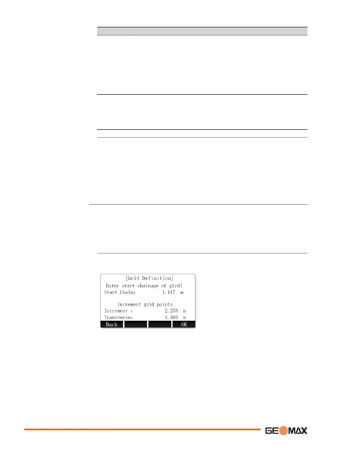
The Stakeout Grid subapplication calculates and displays the stakeout elements for the points on
the grid. The grid is defined without boundaries. It can be extended over the first and second
base points of the reference line.
Defining the grid
1. Use the UP/DOWN keys to select an editable field.
Enter start chainage, increment and transverse to define the grid points.
2. To start staking out the grid points, press OK.
Stakeout grid
78 Application
 Loading...