1-3
Configuration Example
Network requirements
For a user to manage Switch A remotely through Telnet, these requirements are to be met: Switch A has
an IP address, and the remote Telnet user is reachable.
You need to configure the switch as follows:
z Assigning an IP address to the management VLAN interface on Switch A
z Configuring the default route
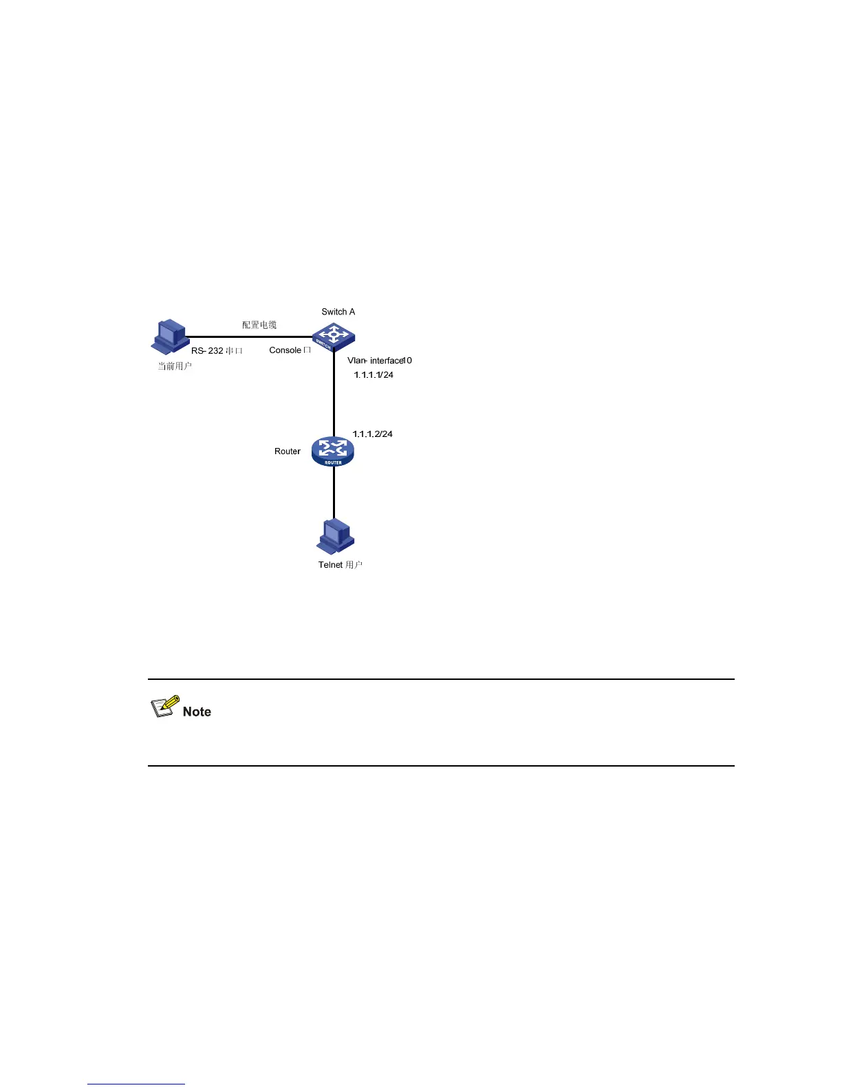
Network diagram
Figure 1-1 Network diagram for management VLAN configuration
Configuration procedure
Perform the following configurations after the current user logs in to Switch A through the Console port.
# Enter system view.
<Sysname> system-view
# Create VLAN 10 and configure VLAN 10 as the management VLAN.
[Sysname] vlan 10
[Sysname-vlan10] quit
[Sysname] management-vlan 10
# Create the VLAN 10 interface and enter VLAN interface view.
[Sysname] interface vlan-interface 10
# Configure the IP address of VLAN 10 interface as 1.1.1.1/24.
 Loading...


