1-7
Table 1-11 Display PoE configuration
Operation Command Description
Display the PoE status of a specific port
or all ports of the switch
display poe interface
[ interface-type interface-number ]
Display the PoE power information of a
specific port or all ports of the switch
display poe interface power
[ interface-type interface-number ]
Display the PSE parameters
display poe powersupply
Display the status (enabled/disabled) of
the PoE over-temperature protection
feature on the switch
display poe
temperature-protection
Available in any
view
PoE Configuration Example
PoE Configuration Example
Networking requirements
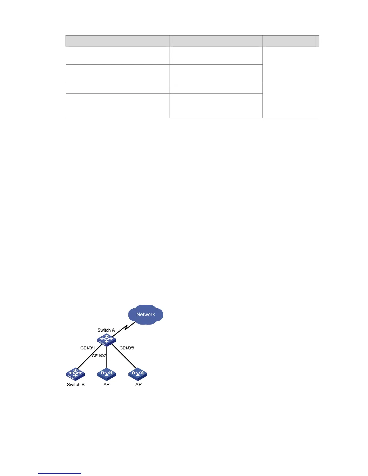
Switch A is an S5100-SI/EI series Ethernet switch supporting PoE, Switch B can be PoE powered.
z The GigabitEthernet 1/0/1 and GigabitEthernet 1/0/2 ports of Switch A are connected to Switch B
and an AP respectively; the GigabitEthernet 1/0/8 port is intended to be connected with an
important AP.
z The PSE processing software of Switch A is first upgraded online. The remotely accessed PDs are
powered by Switch A.
z The power consumption of the accessed AP is 2,500 mW, and the maximum power consumption
of Switch B is 12,000 mW.
z It is required to guarantee the power feeding to the PDs connected to the GigabitEthernet 1/0/8 port
even when Switch A is under full load.
Networking diagram
Figure 1-1 Network diagram for PoE
Configuration procedure
# Upgrade the PSE processing software online.
<SwitchA> system-view
[SwitchA] poe update refresh 0290_021.s19
 Loading...


