1-5
Network diagram
Figure 1-3 Network diagram for IP address configuration
Configuration procedure
# Configure an IP address for VLAN-interface 1.
<Switch> system-view
[Switch] interface vlan-interface 1
[Switch-Vlan-interface1] ip address 129.2.2.1 255.255.255.0
IP Address Configuration Example II
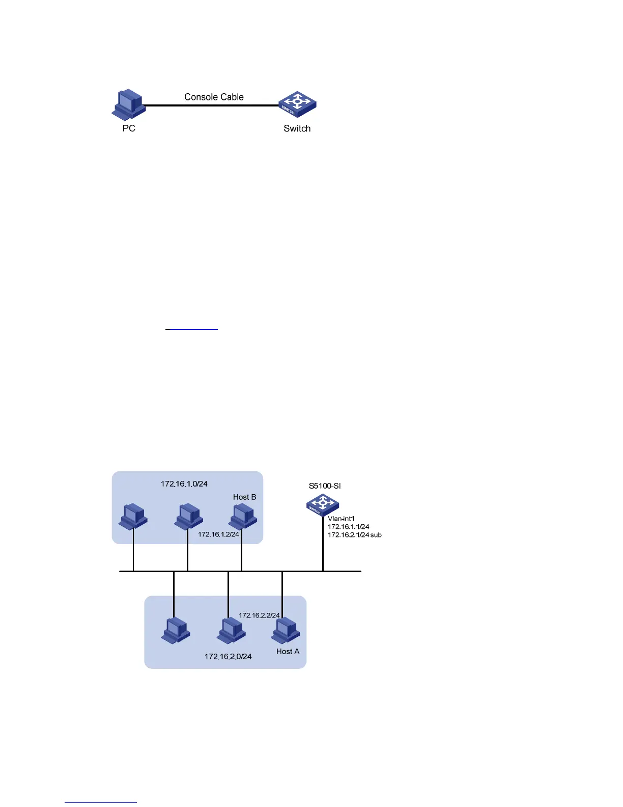
Network requirements
As shown in Figure 1-4, a port in VLAN 1 on a S5100-SI is connected to a LAN comprising two
segments: 172.16.1.0/24 and 172.16.2.0/24.
To enable the hosts on the two network segments to communicate with the external network through the
switch, and the hosts on the LAN can communicate with each other, do the following:
z Assign two IP addresses to VLAN-interface 1 on the S5100-SI.
z Set the S5100-SI as the gateway on all PCs in the two networks.
Network diagram
Figure 1-4 Network diagram for IP address configuration
Configuration procedure
# Assign a primary IP address and a secondary IP address to VLAN-interface 1.
<S5100-SI> system-view
 Loading...


