2-6
z The devices within each VLAN can communicate with each other but that in different VLANs
cannot communicate with each other directly.
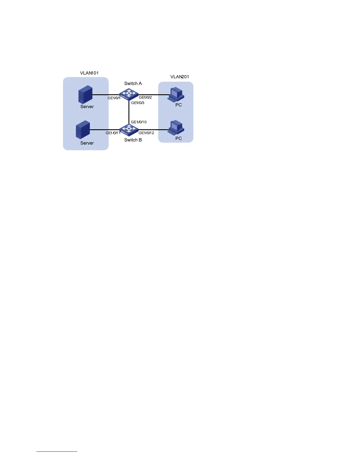
Network diagram
Figure 2-1 Network diagram for VLAN configuration
Configuration procedure
z Configure Switch A.
# Create VLAN 101, specify its descriptive string as “DMZ”, and add GigabitEthernet1/0/1 to VLAN 101.
<SwitchA> system-view
[SwitchA] vlan 101
[SwitchA-vlan101] description DMZ
[SwitchA-vlan101] port GigabitEthernet 1/0/1
[SwitchA-vlan101] quit
# Create VLAN 201, and add GigabitEthernet1/0/2 to VLAN 201.
[SwitchA] vlan 201
[SwitchA-vlan201] port GigabitEthernet 1/0/2
[SwitchA-vlan201] quit
z Configure Switch B.
# Create VLAN 101, specify its descriptive string as “DMZ”, and add GigabitEthernet1/0/11 to VLAN
101.
<SwitchB> system-view
[SwitchB] vlan 101
[SwitchB-vlan101] description DMZ
[SwitchB-vlan101] port GigabitEthernet 1/0/11
[SwitchB-vlan101] quit
# Create VLAN 201, and add GigabitEthernet1/0/12 to VLAN 201.
[SwitchB] vlan 201
[SwitchB-vlan201] port GigabitEthernet 1/0/12
[SwitchB-vlan201] quit
z Configure the link between Switch A and Switch B.
Because the link between Switch A and Switch B need to transmit data of both VLAN 101 and VLAN
102, you can configure the ports at the end of the link as trunk ports and permit packets of the two
VLANs to pass through.
 Loading...


