Chapter 3 System Installation with the Content-
Server 3000 Series
© 2017 Harmonic Inc. All rights reserved. 91 Harmonic MediaGrid Release 4.1
Connecting the Harmonic MediaGrid 3000 System Components
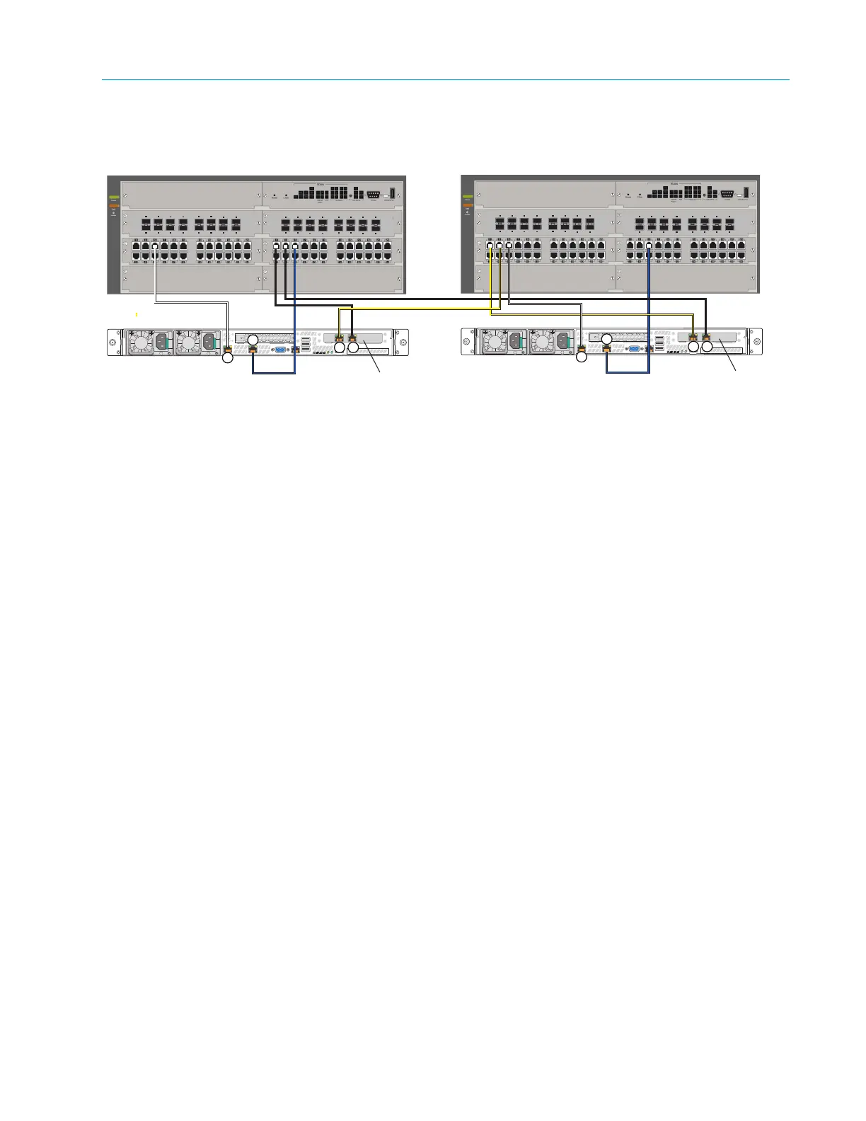
Figure 3–21 shows a detail of the ContentDirector connections to network switches across two
sites.
Figure 3–21: ContentDirector and Network Switch Connections in Stretch Cluster
To connect ContentDirectors to network switches in a stretch cluster:
1. Starting with the ContentDirector at Site 1, connect a yellow fiber optic cable to NIC 3.
Connect the other end of the cable to an open port on the first network switch module at Site
2. This will be used for Private VLAN 1.
2. Connect a black fiber optic cable to NIC 2 on the ContentDirector at Site 1. Connect the
other end of the cable to an open port on the second network switch module at Site 1. This
will be used for Private VLAN 2.
3. Connect a white Ethernet cable to NIC 0 on the ContentDirector at Site 1. Connect the other
end of the cable to an open port on the first network switch module at Site 1. This will be
used for the Public VLAN.
4. Connect a blue Ethernet cable to NIC 1 on the ContentDirector at Site 1. Connect the other
end of the cable to an open port on the second network switch module at Site 1. This will also
be used for the Public VLAN.
5. For the ContentDirector at Site 2, connect a yellow fiber optic cable to NIC 3. Connect the
other end of the cable to an open port on the first network switch module at Site 2. This will
be used for Private VLAN 1.
6. Connect a black fiber optic cable to NIC 2 on the ContentDirector at Site 2. Connect the
other end of the cable to an open port on the second network switch module at Site 1. This
will be used for Private VLAN 2
7. Connect a white Ethernet cable to NIC 0 on the ContentDirector at Site 2. Connect the other
end of the cable to an open port on the first network switch module at Site 2. This will be
used for the Public VLAN.
8. Connect a blue Ethernet cable to NIC 1 on the ContentDirector at Site 2. Connect the other
end of the cable to an open port on the second network switch module at Site 2. This will also
be used for the Public VLAN.
For assistance with configuring a stretch cluster, contact Technical Support.
Site 1
Site 2
Fiber optic
network card
Fiber optic
network card
3
4
5
6
7
8
1
2
11
12
13
14
15
16
9
10
10-GbE SFP+ Ports
3
4
5
6
7
8
1
2
11
12
13
14
15
16
9
10
10-GbE SFP+ Ports
ContentDirector
3 2
0
1
3
4
5
6
7
8
1
2
11
12
13
14
15
16
9
10
10-GbE SFP+ Ports
3
4
5
6
7
8
1
2
11
12
13
14
15
16
9
10
10-GbE SFP+ Ports
ContentDirector
3 2
0
1