Appendix A Legacy Hardware Platforms
© 2017 Harmonic Inc. All rights reserved. 307 Harmonic MediaGrid Release 4.1
ContentDirector 1000E and High Performance ContentDirector 2000B
Rear Panel Components
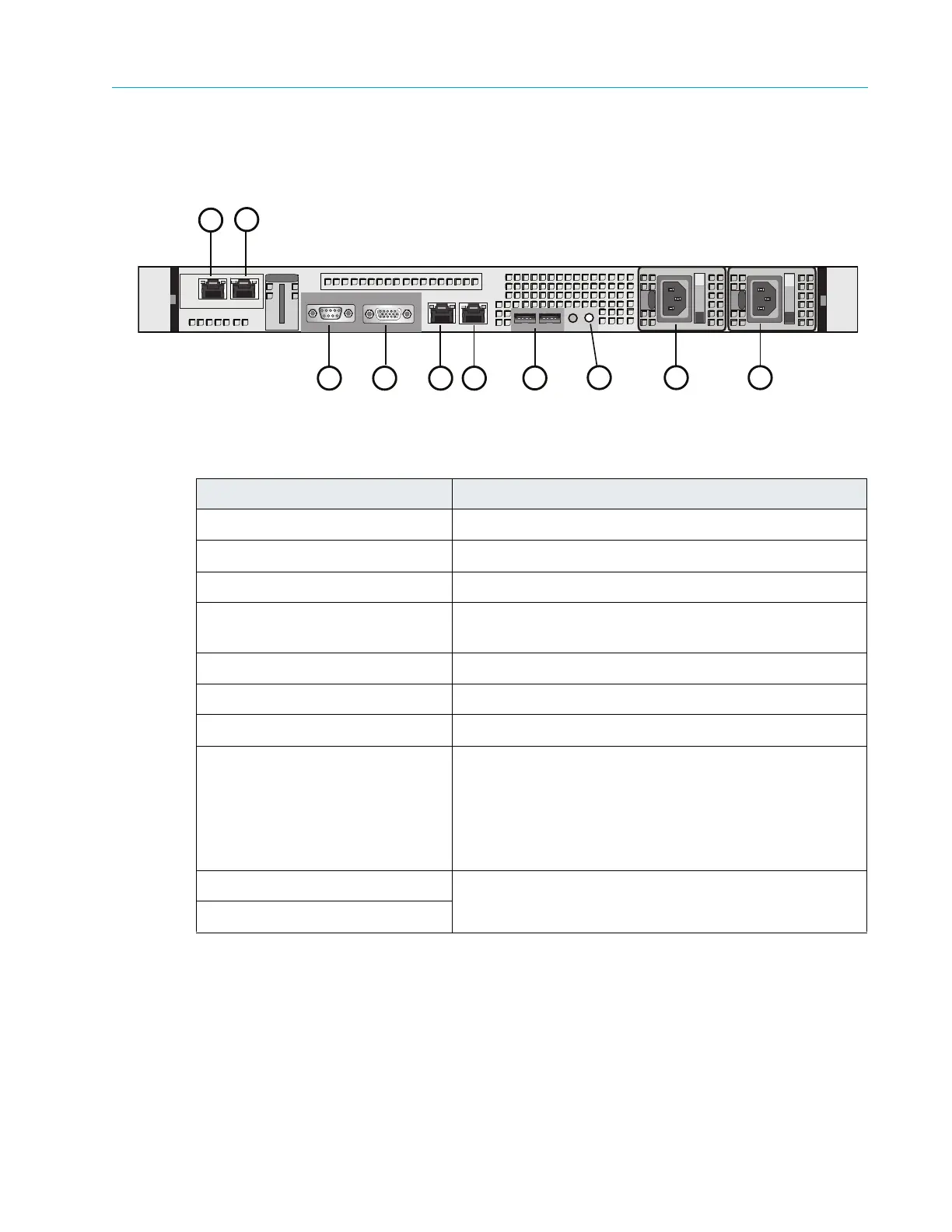
Figure 9–6 and Table 9–7 describe the rear panel view of the ContentDirector 1000E and 2000B.
Figure 9–6: Rear View of ContentDirector
Table 9–7: Rear panel components
Power Supply Indicator/Handle
Figure 9–7 and Table 9–8 describe the typical Redundant Power Supply Indicator/Handle and its
functions.
Indicator, Button, or Connector Description
1. NIC 3 connector Use for Gigabit Ethernet connection to switch.
2. NIC 2 connector Use for Gigabit Ethernet connection to switch.
3. Serial connector Use to connect a serial device to the system
4. Video connector Use to connect a monitor to the system (for maintenance
only).
5. NIC 0 connector Use for Gigabit Ethernet connection to switch.
6. NIC 1 connector Use for Gigabit Ethernet connection to switch.
7. USB connectors (2) Used for maintenance purposes only.
8. System identification button Both the SystemManager application and the system
identifica
tion buttons on the front and back panels can be
used to locate a particular system within a rack. When
one of these buttons is pressed, the ID buttons on the
front and rear panels flash until one of the buttons is
pressed again.
9. Power supply 1 Dual redundant power supplies pr
ovide
power to the
system.
10. Power supply 2
3
1
2
5
4
8 9
7
10
6