Chapter 8 Hardware Reference
© 2017 Harmonic Inc. All rights reserved. 229 Harmonic MediaGrid Release 4.1
ContentDirector 1000F and High Performance ContentDirector 2000C
Rear Panel Components
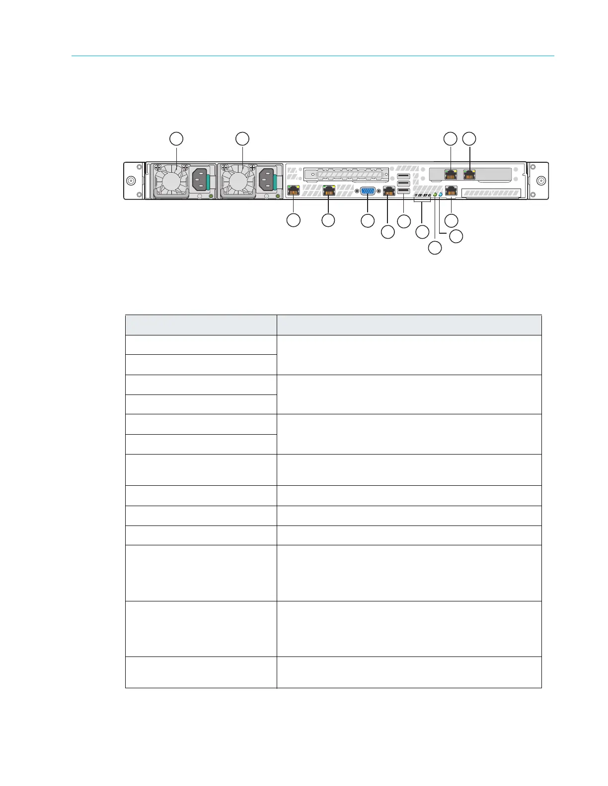
Figure 8–6 and Table 8–7 describe the rear panel view of the ContentDirector 1000F and 2000C.
Figure 8–6: Rear View of ContentDirector
Table 8–7: Rear Panel Components
Indicator, Button, or Connector Description
1. Power supply 1 Dual redundant power supplies provide
power to the
system.
2. Power supply 2
3. NIC 3 Connector
Use for Gigabit Ethernet connection to switch (private
VLAN).
4. NIC 2 Connector
5. NIC 0 Connector Use for Gigabit Ethernet connection to switch (public
VLAN).
6.
NIC 1 Connector
7. Video connector Use to connect a monitor to the system (for maintenance
only).
8. RJ-45 serial port Serial cable is not provided.
9. USB ports (3) Used for maintenance purposes only.
10. Diagnostic LEDs For Service only.
11. System Status LED Located on the back edge of the server board, this LED
matche
s the state of the System Status LED on the front
Control Panel. Refer to Table 8–5 for a description of each
LED state.
12 . S y s t e m I D L E D Located on the back edge of the server board, this LED
match
e
s the state of the System ID LED on the front
Control Panel. When that button is pushed, this LED
flashes blue until the button is pressed again.
13 . Baseboard Management
Console (BMC) connector
Do not use.
2
1
5
3
4
6
7
8
9
10
11
12
13