Chapter 8 Hardware Reference
© 2017 Harmonic Inc. All rights reserved. 230 Harmonic MediaGrid Release 4.1
ContentDirector 1000F and High Performance ContentDirector 2000C
Power Supply Indicator/Handle
Figure 8–7 and Table 8–8 describe the typical Redundant Power Supply Indicator/Handle and its
functions.
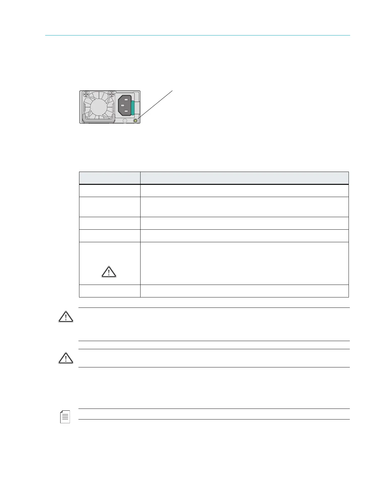
Figure 8–7: ContentDirector Power Supply Indicator/Handle
Table 8–8: Power Supply Indicator Pattern
CAUTION: When correcting a power supply mismatch, replace only the power supply with the flashing
indicator. Swapping the opposite power supply to make a matched pair can result in an error condition and
unexpected system shutdown. To change from a High Output configuration to a Low Output configuration
or vice versa, you must power down the system.
CAUTION: AC power supplies support both 220 V and 110 V input voltages. When two identical power
supplies receive different input voltages, they can output different wattages, and trigger a mismatch.
ContentDirector NIC Indicators
Each NIC on the rear panel has two indicators that provide information on connection status and
speed. Refer to Figure 8–8 and Figure 8–9.
NOTE: The indicator codes for NIC 0 and NIC 1 differ from the indicators codes for NIC 2 and NIC 3.
Figure 8–8: ContentDirector NIC 0 and NIC 1 LED Indicator Codes
Indicator Pattern Condition
Not lit AC power is not connected.
Steady green A valid power source is connected to the
power supply and the power
supply is operational.
Blinks green (1Hz) AC power is connected but operating
in a cold redundant state.
Blinks green (2Hz) Power supply firmware is updating.
Blinks amber A problem with the power supply has occurred
but the power supply is
still functional.
CAUTION: If two power supplies are used, they must be of the same
type and have the same maximum output power.
Steady amber A power supply failure has occurred, causing it to shut down.
Power Supply Status Indicator